I just added the trimmer in the bias circuit, and measured the current with an A-meter on the supply. I also did some distortion measurements, and it seemed there was diminishing return increasing the current above 0,4A.
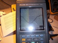
I have also checked this amp with square wave in and the HF capacitors on input and output disconnected, and it has some strange peaking behavior on the positive flank. The peaking increases with output level/current. Same behavior on the L12-2, seems something is not 100% right with the stability.
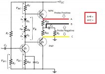
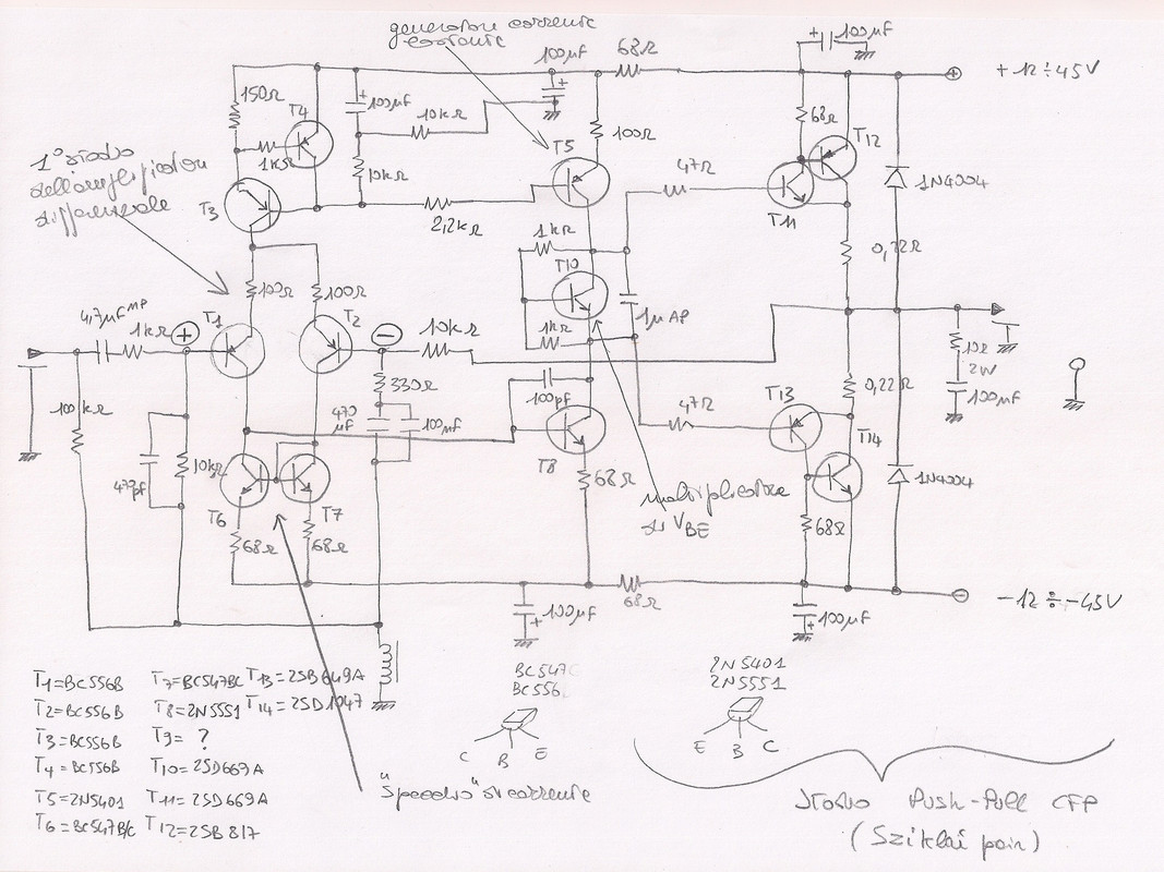
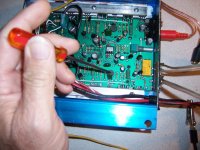
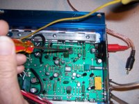
Could you tell me more about it? Did you measure the current between the source output and the amplifier voltage input? Could you measure the bias the way I measure it and give me the values? I'm sending an image showing how I measure the bias. I use the multimeter on the DCV scale set to 200mv. If you can measure this way and give me the values that resulted, I will be very grateful. Thank my friend
Attachments
I just added the trimmer in the bias circuit, and measured the current with an A-meter on the supply. I also did some distortion measurements, and it seemed there was diminishing return increasing the current above 0,4A.
I have also checked this amp with square wave in and the HF capacitors on input and output disconnected, and it has some strange peaking behavior on the positive flank. The peaking increases with output level/current. Same behavior on the L12-2, seems something is not 100% right with the stability.
You are probably seeing what is call 'gm doubling' where increased bias actually makes crossover distortion worse (it also usually results in increases in other distortions).
It's also a CFP design which doesn't need a lot of bias.
I can't measure it, because the amp is disassembled now, and I used higher resistance resistors (0,27ohm). I found the sound a little bit nicer with increased emitter resistors.
If you have 0,15ohm emitter resistors and 0,4A the voltage over one resistor will be 60mV (A to B), and over both resistors 120mV (A to C).
You should check this again when the heat sink is warm.
If you have 0,15ohm emitter resistors and 0,4A the voltage over one resistor will be 60mV (A to B), and over both resistors 120mV (A to C).
You should check this again when the heat sink is warm.
You are probably seeing what is call 'gm doubling' where increased bias actually makes crossover distortion worse (it also usually results in increases in other distortions).
It's also a CFP design which doesn't need a lot of bias.
The peaking was independent of bias, but increased with amplitude, and only on the positive flank.
I increased the Iq looking at FFT in ARTA, and could see the distortion almost disappear on low output levels working in class A. Working in class B at higher levels, distortion was still basically the same as the low Iq setting, so the only downside I could see was more heat. Of course, power supply needs to have decent caps for ripple etc.
As a side note, I have been looking at amp compensations a little bit, and it seems this is always the same 100p miller cap on all LJM amp schematics I have seen, so I think he could have spent some more time on that.
Hello everybody.
I too, like many of you, am playing with this small but very efficient amplifier.
At the lowest voltages, the quiescent current of the amps actually stops at about 30mA, but as soon as the voltage rises, also to obtain more power, the quiescent current rises and even a lot.
Not wanting to polarize the final transistors in class A, I too have adjusted the resistance between the base and the emitter of the VCE multiplier, obtaining the correct quiescent current at +/- 40V of power supply.
What I haven't read from you is if the 2N5401 transistor overheats.
Mine yes, and by touching it it releases part of the heat to the finger, allowing it to vary to the quiescent current of the amps by a few mA.
Could you confirm this behaviour ?
Bias measurement
Hello,
I am ready to power my amp and adjust the bias (2k trimer mod done). I saw in a previous post (attached drawing) that I have to set bias to 10mv but is it between the 2 collectors (Q2 / Q10) or between one of the collector and the 0v?
Thank you,
Didier
Hello,
I am ready to power my amp and adjust the bias (2k trimer mod done). I saw in a previous post (attached drawing) that I have to set bias to 10mv but is it between the 2 collectors (Q2 / Q10) or between one of the collector and the 0v?
Thank you,
Didier
 The image for the above post.
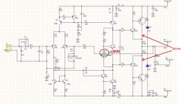
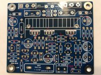
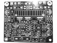
Component location on MX50SE board
Hello all... I used the schematic that slowhands uploaded to this thread...
MX50SE LJM 2015
and labeled the board with component locations.
I just got the boards last week and purchased a set of 2sa1186 and 2sc2343 from Digi-Key.
One question is on the schematic it shows R3 and R29 as 68 ohm but my board shows them at 47 ohm. Should I leave them at 47?
Thanks all for all the info on these boards..
Hope it helps someone.
Attachments
I would leave them at 68 ohm, the final transistors in this way would dissipate more power and the drivers lower. Be aware that D1 and D2 are both reversed: if they were connected that way, there would be a decent bang when you feed the amp.
Maybe that in your interpretation of the PCB maybe you are confusing R5 with R3 and R14 with R29 ?
Maybe that in your interpretation of the PCB maybe you are confusing R5 with R3 and R14 with R29 ?
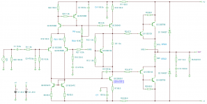
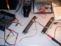
MauroDiY... Do you think I should try some pairs of new old stock 2SC5200 and 2SA1943 or 2SA1302 and 2SC3201 that I've had for years when I repaired soundstream amps? I will be using a 250va 30-0-30 toroid. +-42vdc
MauroDiY... Do you think I should try some pairs of new old stock 2SC5200 and 2SA1943 or 2SA1302 and 2SC3201 that I've had for years when I repaired soundstream amps? I will be using a 250va 30-0-30 toroid. +-42vdc
In my humble opinion, +-42V is a little bit too much high supply at power rails, T5 in the schematic I provide below gets hot if you push over +-30V in my amps. Furthermore, the more T5 gets hot the more the idle current rises thru power bjts.
I think if you wanted increase the supply voltage to +-42V, you have to trim the bias current of the power bjt, reconducting it to 30mA, modifying ohmic value of resistors around T9 on the schematic annexed to this post.
MauroDiY... Do you think I should try some pairs of new old stock 2SC5200 and 2SA1943 or 2SA1302 and 2SC3201 that I've had for years when I repaired soundstream amps? I will be using a 250va 30-0-30 toroid. +-42vdc
I would to replace power bjts with a 2SC5200-2SA1943 pair or TTC5200-TTA1943, too. Just bought a few couple of TTC5200-TTA1943.
Why ? Becouse they seem more robust looking at the datasheets. I haven't already tried, but in my opinion there isn't any reason wht they wont work good, just think we have to check the idle current.
I did so, already had a toroidal 500VA 30+30Vca (42+42Vcc) transformer, but bought the two toroidal you see in the picture 160VA 19+19Vca (27+27Vcc potentially a bit more of 40W on 8Ohm by my amps in a pure dual mono).
This supplier on Amazon have them: Trasformatore Toroidale 160 VA 2 x 115 V: 2 x 18 V: Amazon.it: Commercio, Industria e Scienza
This supplier on Amazon have them: Trasformatore Toroidale 160 VA 2 x 115 V: 2 x 18 V: Amazon.it: Commercio, Industria e Scienza
One more quick question.... C3 as shown is a 470uf/16v and I thought I read that it should be changed to 1000uf/6.3v. I can't remember the reason why. More bass?
Thanks
Thanks
Better sound with R3 & R29 (base stoppers) at 100Ω and R10 150Ω also try R22 at 100Ω for your taste.
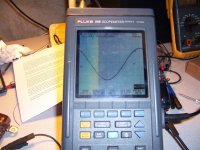
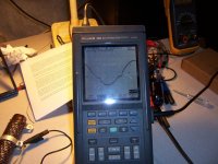
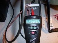
Bias adjust
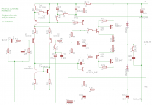
One other way to check bias.
One other way to check bias.
Attachments
- Home
- Amplifiers
- Solid State
- LJM MX50 kit amp