What is this l12-2 Pcb? New version? Or modified by yourself? If could please share detailsHello,
here is the second part of my "making of".
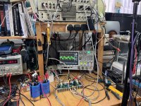
Interior of the amplifier box (with the soft start circuit in the middle back, the shielded transformer of the speakers protection circuit, the speakers protection circuit in the middle and the amplifiers PCB mounted on heatsinks on the sides).
View attachment 1276729
Other view of the components with the AC power filter on the left (in a metallic box).
View attachment 1276731
The speakers protection circuit.
View attachment 1276732
The soft start with thermal protection circuit with the shielded transformer for the speakers protection circuit.
View attachment 1276733
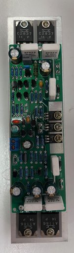
The left channel amplifier PCB with his heatsink before mounting.
View attachment 1276736
The same element installed in the box (with a temperature sensor on the right)
View attachment 1276738
View from the back of the amplifier and the PSU.
View attachment 1276739
View from the front (with amplifier working).
View attachment 1276740
Now I must build the DAC / Preamplifier / volume control...
Thank you every one in this thread for their advice and help.
I can't believe I bought the kit (LJM L12-2 x2) in 2015 and just tested one of them today. Time flies!
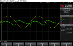
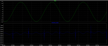
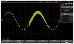
I use a bench DC supply to set the DC 30Vx2. In addition, a pair of 68000 uF reservoir caps are used. As shown in the picture, the wiring is just aimed at preliminary test.
The scope screen capture shows the 10W, 1 kHz waveform across an 8 Ohm resistor load. The green curve is the distortion residual from the AP-S1.
A quick THD+N vs freq. at the power level was performed to see if there is anything not normal. So far so good.
Attachments


Hi,
I also had green PCB L12-2s ... which after LJM are Clones or Fakes.
I was lucky that my Fakes work fully ok so far ... others reported issues with theirs.
So next time You might want to look for the blue PCB L12-2s with LJMs Panda-Logo on ... though it rather looks like Homer Simpson to me 😉
jauu
Calvin
Indeed dear Panson, but I still often get back into "time machine" to read quite few of your "old" posts. Quite educational stuff. Thank you.Time flies!
For example your thread:
TDA7293 single, bridge, parallel from summer of 2011 is still quite interesting.
Motivated by that post I have made four parallel TDA7293 amplifiers with decent performance.
Even Michael Beeny, who loved his L12-2 found parallel TDA7293 much better amplifier.
I was able to attain results comparable to these you published in 2011, shown in a graph below. In my view parallel TDA7293 outmerforms L12-2 and can be easily expanded into a decent high power HiFi amplifier by bridging and paralleling.
Please, your thoughts - you have tested them both.
Performance of TDA7293 in parallel measured by Panson in summer 2011
Last edited:
Hi Berlusconi,
Thanks for your kind words. Great to hear you have good results with the chip-amp.
I need to read the thread to recall what I did before. 😅 I have been focusing on electro-acoustic since 2011. All the amp stuffs were gradually put into the store room. Luckily, my AP-S1 is still strong. Now I want to resume my teenage hobby.
How come I did not make THD vs freq? I probably need to find the board and get the curve measured.
Let me make more tests on this L12-2 board. I may then able to compare them technically.
From an educational point of view, L12-2 wins. We can simulate it and have more fun on mods. 😀
Last edited:
It might be interesting to see what the influence of the fluctuation of the idling current is on THD.
A measurement on the bandwith would also be great to see.
A measurement on the bandwith would also be great to see.
Hi Calvin,I also had green PCB L12-2s ... which after LJM are Clones or Fakes.
Thanks for your info. I bought the kit from LJM TaoBao shop in 2015. At the time, the board was green and without the logo. The current board shown in the shop is blue and with the logo.
I think this is the genuine LJM shop on TaoBao.
The circuit is created in LTspice for simulations. Here are some preliminary results.
Output waveform of 1 kHz, 12 W across an 8 Ohms load, the current of the upper- and lower-half of the output stage and the corresponding distortion residual.
The other graph shows THD vs Freq for 12 W/8 Ohm.
Output waveform of 1 kHz, 12 W across an 8 Ohms load, the current of the upper- and lower-half of the output stage and the corresponding distortion residual.
The other graph shows THD vs Freq for 12 W/8 Ohm.
Attachments
I'm in the US, but there are a number of good sellers on eBay. Here is one I have bought from and everything worked as promised. eBay L12-2 YMMV of course. Make sure you see the Panda in the corner of the board so you are getting the latest version.Hi,
good info 👍
I wished LJM would offer another webshop possibilty ... Taobao is difficult ... almost impossible for me anyway ... to access here.
Alixpress or ebay would reach out to a more global customer list.
jauu
Calvin
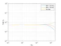
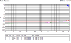
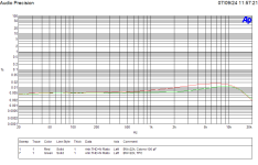
Just to show the importance of 0.1 uF caps (or similar) across the main reservoir caps (well, everybody knows) in the test.
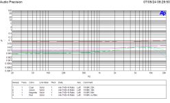
The supply was initially without the 0.1 uF caps. The THD vs Freq for 1W/8Ohm is shown in the left figure. THD at 2 kHz with 22 K BW filter is nearly 0.01 %. When the 0.1 uF caps are added, the THD is reduced to about 0.008 %.
The supply was initially without the 0.1 uF caps. The THD vs Freq for 1W/8Ohm is shown in the left figure. THD at 2 kHz with 22 K BW filter is nearly 0.01 %. When the 0.1 uF caps are added, the THD is reduced to about 0.008 %.
Attachments

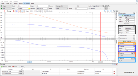
Simulation shows the phase margin is about 30 deg without the dominant/Miller cap at the VAS. Simulation shows a Cdom = 6.8 pF giving a PM of 43 deg.
I don't have 6.8 pF around. Instead, a 10 pF cap is added to the board for testing. THD increases due to the reduction of the loop gain.
Figures: Loop-gain simulation with 6.8 pF, THD vs Freq for 1W/8 Ohms with Cdom = 10 pF, and loo-gain comparison for no Cdom and Cdom=6.8 pF. There is about 7 dB gain difference from 10 kHz to 20 kHz.
Attachments
Last edited:
Correction: The board comes with a Cdom = 100 pF. There is not need to add a Cdom.
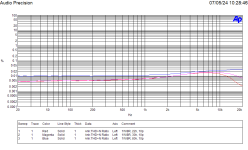
If the original Cdom is replaced with the 10 pF, the amplifier is unstable as shown in the figure. It is stable for using 20 pF. The THD vs Freq for 1W/8 Ohms is given in the other figure.
The board with Cdom = 20 pF will be tested for reactive loads.
If the original Cdom is replaced with the 10 pF, the amplifier is unstable as shown in the figure. It is stable for using 20 pF. The THD vs Freq for 1W/8 Ohms is given in the other figure.
The board with Cdom = 20 pF will be tested for reactive loads.
Attachments
Last edited:
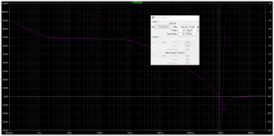
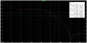
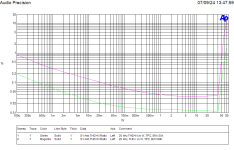
I used the analog discovery 2 (AD2) network analyzer to measure the loop gain of the board with the original Cdom = 100 pF. PE-51687 current sense transformer was employed for signal injection. The result is shown in the figure below. The phase margin is 22 deg. This seems to be not sufficient.
The Cdom creates a corner frequency at 1.27 kHz. Reduction of the loop gain causes the THD to increase vs frequency as seen in the previous measurements.
The AD2 appears to fulfill the loop-gain measurement task.
The Cdom creates a corner frequency at 1.27 kHz. Reduction of the loop gain causes the THD to increase vs frequency as seen in the previous measurements.
The AD2 appears to fulfill the loop-gain measurement task.
Attachments
This is a Nichicon "Muse" non polarized capacitor, famous for his behaviour with audio signal. In parallel with a Wima capacitor it stops DC voltage without effect on audio bandwith.
- Home
- Amplifiers
- Solid State
- L12-2 CFP Output amp 120W*2 8R