Don't need to change something that work perfect,''larger'' does not means better on circuits,usually means worse!
No,it works like it is with very little distortion.The only improvement can do is to separate signal ground from power ground at pcb point.
It's done and power supply for each channel are totaly separated. I also planned to use two loop breaker circuits (the one designed by Rod Elliott).
I have begin the process of adjusting the bias (R19) because I have seen the same artifact (a pic on the midle of raising front) on square wave than Mister Berlusconi (sine wave seemed good). My power supply is 45v and I have thought that it was the manifestation of a bad crossover setting. Indeed the artifact disapears when the voltage on R31 (emetter of Q10) reaches 35mv (R19 equals 875 Ohms). So it's obvious that the bias setting must always be done according to the power supply voltage if we want a good behaviour of this amplifier.

I have set the bias of the second channel. Here are some screenshots of my tests.

Bias not set (voltage on R 31 = 8.8 mv)

Bias set (voltage on R31 = 15.3 mv)
Responses with 200 mv at the input for 10 Hz, 20 Hz, 100 Hz, Khz, 10 Khz, 20 Khz, 40 Khz and 100 Khz


Responses at 1 Khz for 1v, 2v and 3v (86 W eff on 8 Ohms) at the input.


And the response on sine wave at 1 Khz and 2.7 V at the input (it's the maximum of my scope's capabilities before the screen clipping)

The DC offset at the output is 5.4 mv max.
Now I have ordered a lot of resistors to replace the trimmer with resistor(s) of the good value for the Bias setting.
Then I hope I can send you some pictures of the finished amplifier and my feelling about the sound.
Bias not set (voltage on R 31 = 8.8 mv)
Bias set (voltage on R31 = 15.3 mv)
Responses with 200 mv at the input for 10 Hz, 20 Hz, 100 Hz, Khz, 10 Khz, 20 Khz, 40 Khz and 100 Khz
Responses at 1 Khz for 1v, 2v and 3v (86 W eff on 8 Ohms) at the input.
And the response on sine wave at 1 Khz and 2.7 V at the input (it's the maximum of my scope's capabilities before the screen clipping)
The DC offset at the output is 5.4 mv max.
Now I have ordered a lot of resistors to replace the trimmer with resistor(s) of the good value for the Bias setting.
Then I hope I can send you some pictures of the finished amplifier and my feelling about the sound.
Hello LimOnade,
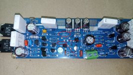
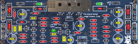
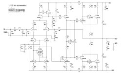
Here are pictures of the PCB with the references (I have done to understand the schematic) and the schematic of version 4 (given by Calvin). References are the same on both. On the schematics polarity of C12 and C13 must be inverted, R2 is 150 Ohms, C6 and C4 are in fact 1µf. It seems that your version have not the same references for Q11, Q13, Q17 and Q19 (2SC1815). Also, R16 is replaced by a capacitor, R7 and Q1 are inverted, C5 is missing. Good luck
Here are pictures of the PCB with the references (I have done to understand the schematic) and the schematic of version 4 (given by Calvin). References are the same on both. On the schematics polarity of C12 and C13 must be inverted, R2 is 150 Ohms, C6 and C4 are in fact 1µf. It seems that your version have not the same references for Q11, Q13, Q17 and Q19 (2SC1815). Also, R16 is replaced by a capacitor, R7 and Q1 are inverted, C5 is missing. Good luck
Attachments
Thanks dasoft, good job, but maybe the author of the thread and boards ljm_ljm can give more info.
You can adjust the R19 resistor to have correct square wave's response because it depends of your power supply voltage (I use 45.5 DC and I had to change the 1K resistor, on the schematic, with 875 and 885 Ohm resistors). Look at my post of 09/28/2023 and the pictures. Ask LJM what is the exact DC power voltage recommanded for the Kit and the bias resistor installed.
Last edited:
If change the c11 100pf miller mlcc capacitor with NP0 silver film ceramic capacitor 82pf the sound change for the better,more open & highs.Don't need to change or add somthing else.Of course separate signal ground & power ground on the board,make a star signal ground on the pot and connect that with a single wire to the psu main ground.Idle current at 55ma per board.
Attachments
I saw some people change the mlcc-electrolytic 1uf capacitors (c4,c6) with mkt or mkp,they not work the same and simply ruin the sound!
Good morning, I'm new here and reading the forum I was not very clear what voltage to use for the transformer, with a voltage of 35-0-35 300VA would be fine? Thank you very much.
yes that voltage will be fine. You should end up with +/-50Vdc (35Vac times 1.414 = 49.5Vdc) to the amplifier boards, and for 2 pair of outputs is safe for 8-ohm speakers, consider going down to +/-45Vdc if you are running 4-ohm speakers. The other consideration is the heatsinks and maintaining air flow across the fins. If fins are open to the air (outside chassis) you can run higher voltage and more demanding speakers, but if you are containing the heatsinks inside the chassis/case, you will need either lower voltage or larger heatsinks to keep it from overheating.Good morning, I'm new here and reading the forum I was not very clear what voltage to use for the transformer, with a voltage of 35-0-35 300VA would be fine? Thank you very much.
Hello, I am building this 4-way amp to power segmented ESL Hybrids with 2 SEAS L26RO4Y 4 Ohms,
I have 2 transformers of 2x35Volts 500VA. In France the mains voltage is 230 Volts instead of 220 Volts from the transformer which gives me an output of 2x53 Volts after rectification, do you think this will not pose a problem or you have to unwind the transformer.
(I have not yet measured the impedance of the ESLs, there are 4 230/2x6volts transformers per channel.)
thank you
Serge B.
- Home
- Amplifiers
- Solid State
- L12-2 CFP Output amp 120W*2 8R