I bought 100 kits of version 3. They all have original Sanken parts and good quality parts. Also build over 30 of these amps so far and both the bias and offset are very close. As is the performance out of the box. I’m happy with these little amps and my clients too. If there is interest i can post all collected versions and mods in this thread.

Two pictures of the box with the transfo, PSU and soft start before wiring. The PCB is now designed with Kicad and I wait for the components to send the process file to the manufacturer.


Hi TarasqueI bought 100 kits of version 3. They all have original Sanken parts and good quality parts. Also build over 30 of these amps so far and both the bias and offset are very close. As is the performance out of the box. I’m happy with these little amps and my clients too. If there is interest i can post all collected versions and mods in this thread.
I would like to know more about the mods.
What speaker protect unit do you use? I have a 2 different LJM amps and also like them. Never had a problem, only good sound.
You need to determine if there is an OUT GND and if there is a DC voltage.Regards,
For the first time in my life (and I'm in my 50's) I assembled an audio amplifier, the LJM L12-2 V4. I have almost no experience in electronics, just the basics of measuring with a DMM and replacing some parts and such.
I used a 300 VA 25-0-25 toroidal transformer, which rectified to 34V DC, I recycled the chassis of an old Sony amplifier and put a speaker protection circuit on it. I plugged it into a bulb current limiter, no speakers, no preamplifier connection, no other audio signals connected and turned it on with no problem: no short circuit, no smoke, no strange noises or smells.👍
For the first minute I measured the DC output and it gave me between 6 and 7mv on each channel. All right!. After a minute it went up a bit to 7-8 mv. I didn't measure it anymore. I left it on, to wait for it to stabilize. So far so good...
But after 2 and a half minutes, the speaker protector activated for a second and then continued normal, but after 10 seconds the same thing happened again, and it was repeated like this every 10 seconds. All without connected speakers or sound source. I turned it off, as something was not right.
Please, I need help to identify what may be happening.
I did the following tweaks, prior to installation:
1. I put X7R capacitors in parallel for all lytics (except C5).
2. Increasing the high-current paths crossection by applying solder.
3. Replaced R19 per Calvin's recommendation, to make BIAS adjustments. I replaced 1K with 1.5K and added 5K potentiometer in parallel. I calibrated it to stay at 1K again, before the first power up.
I also disconnected one card at a time, to see if the problem came from one of them, but the same thing happened with both. I haven't used it without the speaker protection (which could be where the fault is…), but I don't know if this risks burning the boards. I could hook up cheap test speakers to it and see if it makes noise, but only if you tell me if it's safe.
I haven't measured the BIAS yet. I don't have an oscilloscope, just a DMM and a lot of goodwill.😉
Any idea what could be happening? Suggestions?
Thank you.
I think there may be a problem with your speaker protector. I suggest you replace the protective circuit. Or you can show me the photos.
Hello everyone.
I bought 2 boards of this amp on ebay from seller with nickname "toplasers2016", it's ver4 and there is 🐼 in corner and now I would like to know couple questions.
First is there any easy way of testing boards with only multimeter are they legit or I got some fake ones ?
I was measured DC offset on outputs and 1 board is around 12mV and other around 20mV and I was wondering for modification could I just replace R19 with 2k pot without parallel connection with 1.5k resistor and 5k pot and also could I just try to replace some resistors to get on normal DC offset ?
Thanks and please keep in mind I have only multimeter and soldering iron and just a lot of love for electronics and I'm steel noob. 🤓
There should be no problem. I think you can use it directly.Hello everyone.
I bought 2 boards of this amp on ebay from seller with nickname "toplasers2016", it's ver4 and there is 🐼 in corner and now I would like to know couple questions.
First is there any easy way of testing boards with only multimeter are they legit or I got some fake ones ?
I was measured DC offset on outputs and 1 board is around 12mV and other around 20mV and I was wondering for modification could I just replace R19 with 2k pot without parallel connection with 1.5k resistor and 5k pot and also could I just try to replace some resistors to get on normal DC offset ?
Thanks and please keep in mind I have only multimeter and soldering iron and just a lot of love for electronics and I'm steel noob. 🤓
I am LJM. I consider important aspects when designing an amplifier. I didn't pay much attention to adjusting some details. Because not everyone knows how to adjust resistors. This may be complicated for most people.
So I suggest using it directly. of course. A heat sink needs to be installed.
The PCB in Kicad (without mask layers) for larger components and heat sinks.
@dasoft
Great work I must say. Have you thought about possible group buy when you finish this project.
Now, I have something important to say about L12-2.
Important Correction to this thread
Please, read carefully the following text because the entire thread reiterates wrong and confusing information about biassing of the output transistors.
First, to be precise, the L12-2 has CFP output pairs. The optimum quiescent current Iq across each emitter resistor in a CFP configuration is 10.3mA according to DF96 (a three-part article in Wireless World, in Sept, Oct and Nov 2000); Self found 11.5mA.
Also, the measurement procedure proposed here is wrong. Bias adjustments of PNP transistors should be based on voltage measurements between the Vcc and the emitters of Q2 or Q10. Similarly, bias adjustments of NPN transistors should be based on measurements between the Vee and the emitters of Q14 and Q18.
Today I have performed a series of THD measurements for different values of R19. It appears that there are no benefits whatsoever from increasing the quiescent current i.e., replacing the R1 with a potentiometer. The increase of the quiescent current just increases heat dissipation, nothing else, except, maybe, a pleasant effect of Placebo. Furthermore, the original value of the R19 is optimal hence there are no benefits from meddling with it.
LJM is a mature expert and he was constantly reiterating: this amplifier is good by design, there is no need to change anything – he knew better. Meanwhile he incrementally improved L12-2 by replacing C5 with the 33uF capacitor which has significantly reduced low frequency roll-off. Now, frequency response is flat like a pancake even over the boundaries of the audible region. Indeed, there is a slight high frequency boost, but insignificant an beyond the audible region.
Conclusions:
I hope this helps
Great work I must say. Have you thought about possible group buy when you finish this project.
Now, I have something important to say about L12-2.
Important Correction to this thread
Please, read carefully the following text because the entire thread reiterates wrong and confusing information about biassing of the output transistors.
First, to be precise, the L12-2 has CFP output pairs. The optimum quiescent current Iq across each emitter resistor in a CFP configuration is 10.3mA according to DF96 (a three-part article in Wireless World, in Sept, Oct and Nov 2000); Self found 11.5mA.
Also, the measurement procedure proposed here is wrong. Bias adjustments of PNP transistors should be based on voltage measurements between the Vcc and the emitters of Q2 or Q10. Similarly, bias adjustments of NPN transistors should be based on measurements between the Vee and the emitters of Q14 and Q18.
Today I have performed a series of THD measurements for different values of R19. It appears that there are no benefits whatsoever from increasing the quiescent current i.e., replacing the R1 with a potentiometer. The increase of the quiescent current just increases heat dissipation, nothing else, except, maybe, a pleasant effect of Placebo. Furthermore, the original value of the R19 is optimal hence there are no benefits from meddling with it.
LJM is a mature expert and he was constantly reiterating: this amplifier is good by design, there is no need to change anything – he knew better. Meanwhile he incrementally improved L12-2 by replacing C5 with the 33uF capacitor which has significantly reduced low frequency roll-off. Now, frequency response is flat like a pancake even over the boundaries of the audible region. Indeed, there is a slight high frequency boost, but insignificant an beyond the audible region.
Conclusions:
- do not replace R19 .
- do not replace C5 (except you have something very special)
- this amplifier is good as-is by design
I hope this helps
Last edited:
Thank you Berlusconi for your help. I will replace C5 with 220µf Nichicon Muse condensator (I have in stock) and a Wima MKP4 220nf in parallel (to have the flatest response in frequency possible). I have put a 5k trimmer with a 1K resistor in parallel to replace R19 and only pair the two channels. I will also pair the transistors (that I had bought twice). This project will cost a lot of money and is only make for my pleasure (the fun of a self made product). It will not be an competitive amplifier... In the future I can give the Kicad project file and the reference of the elements used to every one interested. One more time thank you for your advices.
Hi, I want to comeback to my posts #560 and #668 about a hum when connecting a preamp. When I connected an op amp as described in post #556 between a preamp and power amp the hum disappeared !!!
Could someone help with clipping issues ? I have 2 boards and on 1 board when testing with oscilloscope clipping starts equal on both rails at 25v rms but on other board clipping on lower rail starts already on less than 10v rms while upper rail remains good till 25v ? What is happening there. I tried already on different transformer and also other rectifier board with 4x4700uF caps but still same. What can I do to check and fix that issue?
Any help is appreciated. 🙂
Any help is appreciated. 🙂
Hi,
reply/add-on to 'important correction to this thread'.
Measuring the individual output transistor bias values requires a decent multimeter, as the voltages are so low.
A typical 3.5...3.3/4 digit cheapo dmm will probabely not be sufficient for this task, resulting in high measurement inconfidence/uncertainty and non optimal biasing
Keep in mind that the displayed value on the dmm display of 1.1-1.2mV may actually be a lot off of the real value.
In the end it's typically just 1% or less of the chosen measurement range of the dmm.
Utilizing the greater voltage for higher dmm readout accuracy was and still is a good reason to at least also check the voltage drops over R13 plus(!) R20.
The reason I modified R19 with a Resistor/Poti-combo was rather not to increase the bias values, but to insure correct and consistant bias values as the bias of the amp modules I had varied largely.
So, if You measure correct and consistant bias values on Your amps then You don't need to modify R19.
If the values differ considerably or are largely off of optimum, then the proposed modification is a good and easy solution.
jauu
Calvin
Forgot to mention testing was done without any dummy load just oscilloscope hooked up directly on output and on input is hooked phone over preamp and on phone was frequency generator, sine wave and same is happening no matter on which frequency. Oscilloscope used for testing was small pocket one from zeewei dso154pro, I know it's not some expensive and extremely accurate but if it worked nice with 1 board than it should do same with other if there is no some issue.Could someone help with clipping issues ? I have 2 boards and on 1 board when testing with oscilloscope clipping starts equal on both rails at 25v rms but on other board clipping on lower rail starts already on less than 10v rms while upper rail remains good till 25v ? What is happening there. I tried already on different transformer and also other rectifier board with 4x4700uF caps but still same. What can I do to check and fix that issue?
Any help is appreciated. 🙂
Ps. Sorry if it's not right place but does anyone have some advice what would be good to do with Kenwood transistors traits, I have 8pcs (4pairs) and would like to know are those worth trying to make some amp or is there some easy circuit for them or maybe someone needs those or anything else?
My PCBs (4Oz) come from PCBWAY...


Now I'm ready to solder the componants.
Now I'm ready to solder the componants.
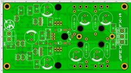
4oz PCB, larger tracks, larger space for 1 w resistors and better capacitors. So not the same PCB...
In addition to the resulting large areas of power circuits, I consider the main mistake to be the change in the location of the three transistors. The transistor - current sensor should be on the same cooling plate with two drivers and be as close to them as possible in order to more accurately read the temperature. And you made this worse with your board compared to the LJM board.
- Home
- Amplifiers
- Solid State
- L12-2 CFP Output amp 120W*2 8R