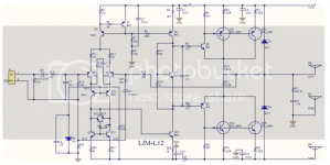
of course, this is a small initial current for the output, but keep in mind that Darlington transistor assemblies are paralleled at the output, with an increase in the initial current, the work of such assemblies, due to their characteristics, is more difficult to make equal.The quiescent current of this board = 16.5 mA, which is very small. This is more in line with class B. Then, I began to look for distortions of the "step". These distortions appeared very well at 100 kHz and very weakly at 20 kHz.
such schemes need to be modified...I might do that, just I have to take the board from the bin where it ended after testing it.
Indeed Hennady 😎such schemes need to be modified...
Obviously you're right, several modifications have already been suggested but I wouldn't bother.
To accomplish that I should have much more knowledge and I am not an expert. But, I have lots of experiences in measuring equipment and I know exactly which parameters should be achieved to have an excellent sound.
Therefore I have abandoned all projects that require lots of design knowledge and efforts and have foccused to selecting projects based on fundamentally proper design.
I have built four amplifiers that could be considered as Hi-Fi and more importantly: they are stable and safe, to avoid smoke and destroyed speakers. Three of them are A-class and one is based on STK 4042Xi which can easily go below 0,01% THD.
Same as with women: some of less attractive may undergo aesthetic surgery but will never surpass a natural beauty. Beauty by the design.
Last edited:
I support. Only with this approach, you can achieve good results in terms of sound quality.Therefore I have abandoned all projects that require lots of design knowledge and efforts and have foccused to selecting projects based on fundamentally proper design.
Dear Gennady and Berlusconi, for me it is also a hobby and I cannot say that I have become a great professional, but I have reached a good level. And I have a sufficient fleet of measuring instruments. With regard to amplifiers, I believe that, personally, I need to constantly improve my level, take new peaks of skill. Train on mockups and finished products and move from simple to complex. And doing the same thing is not interesting! I'm interested in experience and SOUND. And, as practice shows, there are beautiful and ... true-sounding amplifiers. Different people like it in different ways. Depends on your attitude to the sound.
Train on mockups and finished products and move from simple to complex.
I think that only the system method works in audio amplification, that is, there is no point in complicating where it should not be done and there is no point in simplifying where simplicity will correspond to lower quality. The audio amplifier circuit must be balanced in implementation, design, and measurable key characteristics.
The higher level is the level of technology associated to a greater extent with the practical implementation of the product.
Step & Hennady,
Thank you very much for bringing fresh view into this thread dominated with euphoric hymns about the sound quality of L12. At the end of the day it is what it is: "sounds good for the price of a breakfast".
Eactly Step has pointed to the main deficiency:
When a good CRC power supply is used, the result changes signifficantly. (Just look at the graph below, provided by the seller himself). It is true that the boars can achieve relatively low THD values, but one should observe the entire frequency domain to find the reason for bad low frequency response. To illustrate this, I have shown the sellers own measurements. The seller slylly has shown frequency response in a linear graph, but the deficiency is still obvious, though, hidden. Just look at the region below 1KHz, very small but still revealing the problem. Noise is prohibitively high and +N component is not shown fair enough. Why?
Under the "pressure" brains surrender to the Placebo or should I say Snake oil packed in a pretty bottle.
Therefore, honest meassurements are indispensable.
Thanks guys again for the insights into the real value of this board.

Thank you very much for bringing fresh view into this thread dominated with euphoric hymns about the sound quality of L12. At the end of the day it is what it is: "sounds good for the price of a breakfast".
Eactly Step has pointed to the main deficiency:
I did the both meassurement and I know the truth, but I didn't want to spoil the party.This board was tested when powered from a laboratory source. It has a very small level of its own noise.
When a good CRC power supply is used, the result changes signifficantly. (Just look at the graph below, provided by the seller himself). It is true that the boars can achieve relatively low THD values, but one should observe the entire frequency domain to find the reason for bad low frequency response. To illustrate this, I have shown the sellers own measurements. The seller slylly has shown frequency response in a linear graph, but the deficiency is still obvious, though, hidden. Just look at the region below 1KHz, very small but still revealing the problem. Noise is prohibitively high and +N component is not shown fair enough. Why?
Under the "pressure" brains surrender to the Placebo or should I say Snake oil packed in a pretty bottle.
Therefore, honest meassurements are indispensable.
Thanks guys again for the insights into the real value of this board.
Last edited:
I approach this board as a semi-finished product, it is interesting to achieve the desired result. In addition, I see a number of advantages of this board:
1) Before I bought this board, I thought that the amplifier, which takes the signal from collectors, but not from emitters, makes more noise. This amplifier showed that this was not the case.
2) This board is quite stable. The DC output voltage is under 1mV, which is an excellent result!
3) The board has pretty good parameters and sound. I just have to try and refine it to the parameters given by the vendor, or come close to them. That's what I want to do.
First I will measure it with unstabilized power supply to know the real parameters, and then I will try to change the quiescent current and see how it affects the parameters of the amplifier. It's a good subject for experimentation.
This board is quite stable.
can you see the schematic and wiring of the board itself?
P.S. at the beginning of the topic there is a diagram, there are also comments by the author that contradict the diagram ...
Dear colleagues, I did a big test of this board and prepared a lot of material. But in order not to overload the topic, I can make all the material in Pdf format. I just want to say that I do not speak English, I use a translator. I want to ask: what I write is understandable? If I write in Pdf in English, it will be long and there may be errors in translation.
Now part of the answer to the question: the first 3 pictures are not yet tested board. The 4th picture is the tested board. Next is my minilab (#5). #6 is the 36V bipolar transformer and the power supply itself with load protection. #7 - instrument readings: DC voltage at the output of the amplifier (left) and the positive half of the power supply (right).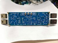
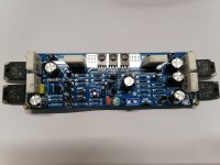
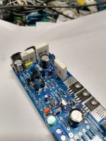
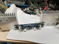
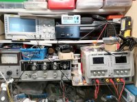
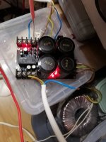
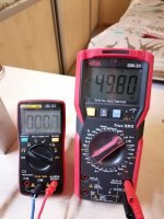
What surprised me: with such a large power supply and small heat sinks of the output transistors, during a long enough test, the heat sink of the load resistor = 8 Ohm/100W was red-hot, but the heat sinks of the output transistors, were warm and not even hot! The output power measured with an oscilloscope = 100 W/8 Ohm/bipolar 50 V supply. A little short of the claimed 120 watts... I still have a lot of pictures, so I'd better put some of them in the second part of the answer, so as not to bother with Pdf...
Now part of the answer to the question: the first 3 pictures are not yet tested board. The 4th picture is the tested board. Next is my minilab (#5). #6 is the 36V bipolar transformer and the power supply itself with load protection. #7 - instrument readings: DC voltage at the output of the amplifier (left) and the positive half of the power supply (right).


What surprised me: with such a large power supply and small heat sinks of the output transistors, during a long enough test, the heat sink of the load resistor = 8 Ohm/100W was red-hot, but the heat sinks of the output transistors, were warm and not even hot! The output power measured with an oscilloscope = 100 W/8 Ohm/bipolar 50 V supply. A little short of the claimed 120 watts... I still have a lot of pictures, so I'd better put some of them in the second part of the answer, so as not to bother with Pdf...
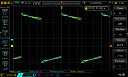
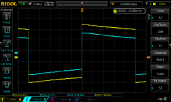
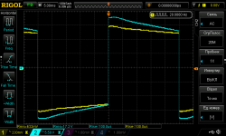
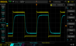
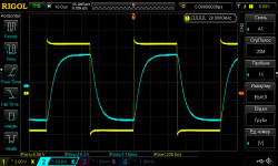
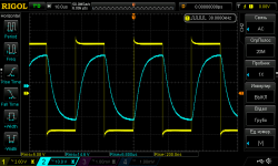
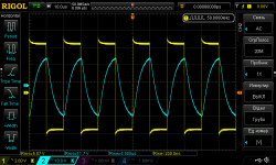
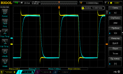
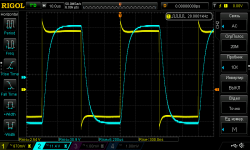
So, the test with bipolar power = 50 V.Recall that in blue is the output signal. The signal before the clip pic 1, then, remembering that they talked about a rectangular signal of large amplitude and low frequency, I did it: pic 2. The stylus was switched to x10. And the input signal = 0.7 V:
pic 3-4. Next, signals of different frequency and amplitude: 5-10 And at the end, test Spectra at 1,5,10 and 50W. The board after the test is working. Nothing happened to it...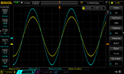
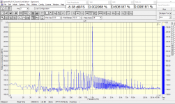
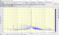
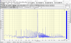
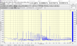 As you can see, according to Spectra's tests, with unstabilized power supply, the harmonic noise grows sharply and the actual noise shelf turns out with the level of -100...110 dB. On the one hand it is not much, but there is a narrowing of the dynamic range and such a forest of harmonics can be heard and can interfere... That's why I prefer stabilized power supply - absolute silence in the speakers!
pic 3-4. Next, signals of different frequency and amplitude: 5-10 And at the end, test Spectra at 1,5,10 and 50W. The board after the test is working. Nothing happened to it...


 As you can see, according to Spectra's tests, with unstabilized power supply, the harmonic noise grows sharply and the actual noise shelf turns out with the level of -100...110 dB. On the one hand it is not much, but there is a narrowing of the dynamic range and such a forest of harmonics can be heard and can interfere... That's why I prefer stabilized power supply - absolute silence in the speakers!
Hi! I want to make everyone happy. Good news. Installing a 15k resistor in parallel to resistor R19 raises the board's quiescent current to 150mA and improves the circuit parameters very well when powered by a stabilized source. I tried to increase the quiescent current to 180mA, but I didn't see a big difference in the graphs. Tomorrow I will see how this improvement will affect the power supply from an unstabilized source.
Hi,
why is the peak level in all four Spectra graphs almost identical?
Between 1W and 50W is a ~17dB difference in voltage level (into 8R).
Do You use a variable gain amplifier as frontend?
If so, would that amplifier be THD transparent at these signal levels?
Second Q is: Do you know the THD-level of the ADC itself?
The THD minimum for the renowned AKM ADC (as used in the RTX and QA Analyzer) appears around -16dBFs and rises considerably above that level.
jauu
Calvin
Hi! I want to make everyone happy. Good news. Installing a 15k resistor in parallel to resistor R19
where is the diagram?
Hi! I use an improvised audio card consisting of a high quality DAC and an Olivin ADC. The description of the Olivin is here: https://forum.vegalab.ru/showthread.php?t=67983&page=4 Author's website: http://www.altor.co/products/test-equipment/olivine
Parameters of the DAC+ADC loop: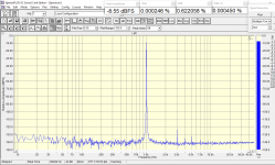
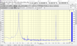
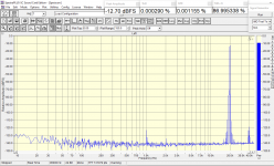
From the pictures:
1) THD test
2) IMD test standard
3) IMD test hard
Here's the table I use: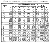 The upper graph is the load resistance, the left graph is the power on the load. Very convenient. At 1 kHz Spectra, after calibrating the loop, you set on the load 8 ohms, with the volume knob the desired output voltage, taken from the values of the table (measured with a multimeter) and automatically get the output power from the table. You don't need to count anything - everything is already calculated. Very convenient. And after the load of 8 ohms, I also have a divider, which I use to adjust the voltage at a given power (I take the values from the table) to a level of -8.4 ... 8.9 dB close to the value of -8.5 dB obtained during calibration. This is my procedure when measuring. One last thing. If the circuit board corresponds to the picture of the author's thread, so does the circuit. It is posted at the beginning of this thread. I did not check it thoroughly, I have no time. But the output stage is correct. I hope my explanations are clear...
I forgot to say: at -8.5 dB, by Spectra, when calibrated, the DAC output: 1.68 V rms
The DAC was bought ready-made, I don't know its circuitry. The chip on the board is 4394 (Or maybe AK4493? I don't remember anymore...). If interested, I can take a picture.
Parameters of the DAC+ADC loop:


From the pictures:
1) THD test
2) IMD test standard
3) IMD test hard
Here's the table I use:
 The upper graph is the load resistance, the left graph is the power on the load. Very convenient. At 1 kHz Spectra, after calibrating the loop, you set on the load 8 ohms, with the volume knob the desired output voltage, taken from the values of the table (measured with a multimeter) and automatically get the output power from the table. You don't need to count anything - everything is already calculated. Very convenient. And after the load of 8 ohms, I also have a divider, which I use to adjust the voltage at a given power (I take the values from the table) to a level of -8.4 ... 8.9 dB close to the value of -8.5 dB obtained during calibration. This is my procedure when measuring. One last thing. If the circuit board corresponds to the picture of the author's thread, so does the circuit. It is posted at the beginning of this thread. I did not check it thoroughly, I have no time. But the output stage is correct. I hope my explanations are clear...
I forgot to say: at -8.5 dB, by Spectra, when calibrated, the DAC output: 1.68 V rms
The DAC was bought ready-made, I don't know its circuitry. The chip on the board is 4394 (Or maybe AK4493? I don't remember anymore...). If interested, I can take a picture.
Last edited:
Yes, as expected, there is a faint background in the speakers if you lean your ear very close. But the sound is not bad even with unstabilized power supply... And even at low volume - powerful bass. It's nice. I expected it to be worse. But even the faint background is bad. On faint sounds, in silence, will interfere. I will listen to it tomorrow at normal volume. Stabilized power is better!
But when I started researching the spectra, I realized there was a problem. Raising the quiescent current also raised the gain of the output stage. The harmonic spectrum became shorter and went more to the low frequencies. That's why the low frequencies played better... Here clearly showed the disadvantage of this solution of the output stage: the amplification of the entire noise spectrum... So it turns out that for this variant stabilized power supply is preferable! This was most apparent at 5W (50 V unstabilized power supply) output power: the low quiescent current: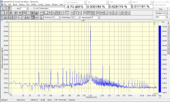
The quiescent current is 0.2 A: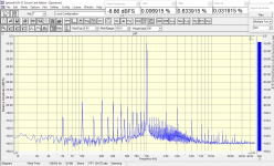 It turns out that for a non-stabilized power supply, the option with a small quiescent current is preferable! So the original version is designed specifically for unstabilized power and that's right!

The quiescent current is 0.2 A:
 It turns out that for a non-stabilized power supply, the option with a small quiescent current is preferable! So the original version is designed specifically for unstabilized power and that's right!
Last edited:
mama mia... ((((To be clear, I used the diagram from response #6:
How do you have so much free time to occupy with nonsense?But when I started researching the spectra, I realized there was a problem.
In this scheme, you first need to remove all children's mistakes, and only then analyze ...
Interesting, interesting... How do you think, Gennady, should the scheme look like, without "childish" mistakes? And what do you consider "childish" mistakes? I am a simple amateur, and I am interested in a different opinion. Or, what answer shows a diagram without "childish" mistakes? I would be grateful for a more detailed answer.
- Home
- Amplifiers
- Solid State
- L12-2 CFP Output amp 120W*2 8R
