Hi dakku. Did this final wiring scheme remove the hum problem that you were plagued with? I have gone to the expense of going to 2x toroidals and 2x PSU. Have not yet done the upgrade, but I will be very depressed if this does not cure the hum problem. By the way from the above diagram, you left the grounding off the Left (black) input? You also did not take the input ground to the green connector on the board but connected it to the star earth point?updated to include a ground to chassis using 10ohm resister in series.
View attachment 1410036
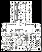
- Star Ground:
- The PSU star ground is used as the central reference point.
- All grounds (amps, RCA, speaker protect module) terminate at this star ground.
- RCA Ground:
- The RCA connectors share a common ground that connects directly to the star ground.
- The amplifiers are connected to the star ground, not directly to the RCA ground.
- Amplifier Grounds:
- Both amplifiers use the star ground as their reference
- Signal ground (from RCA) flows to the star ground and then to each amp ground.
- Speaker Protect Module:
- Each channel of the speaker protect module connects to the corresponding amp’s ground and outputs.
- Ground is isolated for each channel, avoiding direct ground sharing between left and right.
- Chassis Ground:
- The chassis is connected to the PSU star ground via a 10-ohm resistor.
- The chassis is also connected to the mains earth
Many thanks Chalky for tracing this out. I thought the 33uF cap was the input DC blocking cap and not realised the board does not carry one. At least it makes adding a film-type very easy. It would be very useful if you could add to the schematic how the 2 solder pads and through hole are configured as regards the bias control around Q7. It seems LJM has provided these so someone could add a trimmer without needing to remove R10 or R19? Maybe you still will, but the board marking suggests a trimmer of 33-100K Ohms. I'm sure other owners of the V4.2 would find it useful. Many thanksSchematic for L12-2 Ver4.2 as promised.
Hey there,
still a complete Newbie when it comes to electronics, but since I'm currently finishing an ESL-build, I wanted to push my project of the associated amp.
I'm another one of these guys who's trying to copy the Michael Beeny build. I'm really sad to hear that he's not able to continue with his project due to his health issues. I wish you a speedy recovery at this point!
I tried to trace out all the info available in a diagram foolproof for beginners like me. This is only a first attempt while still working through the available info, so I don't expect it to be anywhere near perfection. But maybe this already helps identifying some design issues.
Let me know what you think!

Yes, All looks good....BUT the way I have wired my similar amplifier is 1) The RCA earth gnd. shield is taken all the way to the amp's input block -ve screw. I would not cross-connect them at the socket as you do above, I do not connect the signal earth gnd to anywhere else.... just the co-ax shield from socket to amp input. I have ZERO hum! 2) Many speaker protection boards from China have the earth speaker ground cross connected on the board. If you have dual mono set up with 2x toroidals and 2x PSU you don't want the grounds of the amp speaker cross connected, do you? You can get full earth separation boards on AliExpress.... maybe your one is? Be careful with the trimmer mod. (you highlight the old position above so maybe you intend to do it?) The V4.2 boards have a different component position for R19 and R23... Check with meter that the resistor you are removing is the 1K ohm one rather than the 100 Ohm one that has changed position. PS: I've never used a soft-start board with amps, but your choice of course. 120VA toroidals are maybe a touch small, I used 160VA ones.... Also the output coils seem to be near the O/P sockets... I would also like to know if this is OK to do this rather than have them near the board's O/P tag.

Last edited:
Hello! How does this L12-2 amp(vers 5) compare with A60 or with GB150D or MX50SE. (or another option)which sounds better?I am thinking of buying one board... don't need more than 30-50W of low distortion sound ...if it is more, it is not o problem...Please share your thoughts...Thanks in advance!
I have two of the first boards and with Micheal Beeny's mods done, it works very well. I heard that later sales (showing the same version number) of the boards were OK without mods, so I'm eager to hear peoples views.
Boards arrived. Now is time to put them to work


What package trim pot fits on two SMD pads?Many thanks Chalky for tracing this out. I thought the 33uF cap was the input DC blocking cap and not realised the board does not carry one. At least it makes adding a film-type very easy. It would be very useful if you could add to the schematic how the 2 solder pads and through hole are configured as regards the bias control around Q7. It seems LJM has provided these so someone could add a trimmer without needing to remove R10 or R19? Maybe you still will, but the board marking suggests a trimmer of 33-100K Ohms. I'm sure other owners of the V4.2 would find it useful. Many thanksView attachment 1438665
I never found out. I was hoping LJM would advise us, but as it is, I'm going to use the old way and replace R19 (R23 position on board shown) with a normal trim pot and resistor.What package trim pot fits on two SMD pads?
- Home
- Amplifiers
- Solid State
- L12-2 CFP Output amp 120W*2 8R