Hello,
So this is a duplicate to this post that I can't delete
I got this smps for my l12-2
https://a.aliexpress.com/_EuE444c
The thing is that it does not have any ground connection on the dc side so i grounded my amp boards and speaker output to the socket.
Everything is silent until I turn my dac on. When i do that, i get a hard buzzzz
When i connect my tablet instead of the dac everything is silent. In Guess have a ground loop with the dac.
My question is finally how can I ground the dc side? (Speaker negative and board ground)
So this is a duplicate to this post that I can't delete
Hello,
I got this smps for my l12-2
https://a.aliexpress.com/_EuE444c
The thing is that it does not have any ground connection on the dc side so i grounded my amp boards and speaker output to the socket.
Everything is silent until I turn my dac on. When i do that, i get a hard buzzzz
When i connect my tablet instead of the dac everything is silent. In Guess have a ground loop with the dac.
My question is finally how can I ground the dc side? (Speaker negative and board ground)
Thanks
I got this smps for my l12-2
https://a.aliexpress.com/_EuE444c
The thing is that it does not have any ground connection on the dc side so i grounded my amp boards and speaker output to the socket.
Everything is silent until I turn my dac on. When i do that, i get a hard buzzzz
When i connect my tablet instead of the dac everything is silent. In Guess have a ground loop with the dac.
My question is finally how can I ground the dc side? (Speaker negative and board ground)
The ground of the amp board and loudspeaker negative should be connected to the SMPS ground terminal.
Then just break the ground loop with a USB isolator.
Disconnect the DAC input from the source and check hiss, if no hiss - use usb isolator. If hiss persist - try isolation transformer
Then just break the ground loop with a USB isolator.
Disconnect the DAC input from the source and check hiss, if no hiss - use usb isolator. If hiss persist - try isolation transformer
Thanks tolik,
I can still send the smps back, i will take the same one as you in order to have a straight forward setup
When the jacks are off or the dac not powered there is no noise, it is when the dac is powered that the problems start
I will try disconnecting the usb
I can still send the smps back, i will take the same one as you in order to have a straight forward setup
When the jacks are off or the dac not powered there is no noise, it is when the dac is powered that the problems start
I will try disconnecting the usb
Last edited:
Hello,The ground of the amp board and loudspeaker negative should be connected to the SMPS ground terminal.
Then just break the ground loop with a USB isolator.
Disconnect the DAC input from the source and check hiss, if no hiss - use usb isolator. If hiss persist - try isolation transformer
No luck, i guess it is going back.
Better get the proper SMPS.
Thanks agin
Finally an electonician friend told me I can make the 0 point with 2 transformers. As this one is good quality and dead silent, i will get another one and assemble them like on this schématic

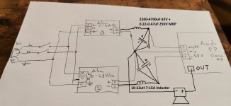
Just pay attention next time you choose a power supply. The one you purchased is a SINGLE output power supply. It is say 0 +50V. It is ok for class D amplifiers, of single-ended linear amps, like Hood 1969.
For a linear amp with bipolar output, a BIPOLAR (or dual, or +/- XX volt) power supply is required. Its output is -50 0 +50V.
This is what I use
https://www.aliexpress.com/item/100...order_list.order_list_main.550.3a131802UWa2u8
One such board can power 2 L12 boards, or with 2 such SMPS, a very nice dual mono configuration is possible.
It is the one I initially planned on talking, then I saw the footprint of the other one and didn't investigate further
Hello ,
Do you think that LTspice simulation for L12-2 V5 as his place in this forum ?
Br
Jacky
Do you think that LTspice simulation for L12-2 V5 as his place in this forum ?
Br
Jacky
Why you need the simulation, while measurements of working device are available?

Add the following models in standars.bjt file :
.model 2SA1186 PNP(Is=100f Eg=1.11 Bf=114 Ise=100f Ne=1.293 Ikf=100 Nk=1.825 Xtb=1.5 Br=25.5 Isc=191f Nc=1.618 Ikr=.971 Rc=65.7m Cjc=525p Cje=500p Tr=1.62u Tf=2.70n Itf=205 Xtf=60.7 Vtf=10 Vceo=150 Icrating=10 mfg=Sanken)
.model 2SC2837 NPN(Is=20f Eg=1.11 Bf=109 Ise=20f Ne=1.306 Ikf=54.21 Nk=1.407 Xtb=1.5 Br=13.7 Isc=335p Nc=1.512 Ikr=.577 Rc=52.2m Cjc=285p Cje=300p Tr=4.42u Tf=1.85n Itf=123 Xtf=297 Vtf=10 Vceo=150 Icrating=10 mfg=Sanken)
Attachments
Once, a group of wise men gathered in a pleasant room, eat delicious foods and drunk fine wine.
After discussing many interesting subjects they addressed anathomy of donkeys. More precisely, they discussed the number of donkeys teeth. They even wanted to consult the Holy Scripture to find out the number of teeth in donkeys mouth.
They could have gone downstairs to the stable and simply count donkeys teeth.
Instead, they used LTSpice to simulate donkeys mouth anathomy. Wise men.
Last edited:
ask Einstein about measuring things.
Oh, forgot that Einstein hadn't the measuring devices required to verify his ideas
Oh, forgot that Einstein hadn't the measuring devices required to verify his ideas
In post 1,075 Tolik has provided us with comprehensible and trustworthy measurements. From these results It is so easy to know everything we need about the subject of this lenghty thread. No further reading is needed. None.
After some absurd statements in posts 1,096 and 1,097, let's get back to the busines as usual.
Modelng is indeed indispensible design tool, both in the stage of conceptual design and then, later, during evaluation of design alternatives.
However, when the final design has been attained and turned into a tangible piece of equipment, modeling can be used just in retrospective: to evaluate how far from reality were design variables and achieved performance parameters? How accurate were our models?
This has nothing to do with relativity theories.
More importantly, measurements provide us an answer to the question: does the design correspond to our design objective? Or simply put: is it worthwhile to make an amplifier from the actual PCB?
Reverse engineering of the PCB is a trivial task, requiring just patience and squandering precious time. Dear Calvin, I do indeed appreciate all your efforts spend to reverse engineer the PCB.
Hi dakku.... Don't bother. I have 2x power units the same type as your single one) and I am having IDENTICAL hum problems as you are. I've spent a day on it but nothing changes the hum. With ONE input connected, on whatever channel, the amp runs with zero hum. When you connect the second input (even with its ground not connected) there is a hum..... I think the ONLY way is to have 2x transformers with the 2 PSUs so each amp is COMPLETELY separate from the other, like Dual Monos in one box.... having suggested that, it would be around 100 quid+ at least, and I'm not absolutely sure even that would take the hum away. I am COMPLETELY baffled and have made lots of power amps without hum problems.... I just do not know what is going on. BTW isn't the input resistor the 33uF solid electrolyte can that is now called C4 rather than C5?... I'm sure LJM has fitted an input blocking cap. NB**** With one toroidal and 2x PSUs they are still connected together by the NEUTRAL centre tap of the 2 windings that will be shared, so there is a link between the GROUNDS that feed each amp board.... the neutral input on the PSU is cross connected to the output GROUND terminals on this design! As said above, the ONLY way to break the GROUNDS is to have 2x transformers and 2x PSUsI am tempted to just buy a 2nd rectifier board and run the two boards from one torodial transformer.
Do you think that should take care of ground issues?
Last edited:
SORRY a mad Typo!... I obviously meant the INPUT DC blocking capacitor! The 33uF is the input capacitor!....Is it not?BTW isn't the input resistor the 33uF solid electrolyte can that is now called C4 rather than C5?.
- Home
- Amplifiers
- Solid State
- L12-2 CFP Output amp 120W*2 8R