It does, but what I also noticed was the 100uF at the bases of the pass transistors. This makes startup take around 4s, and 10uF seems to work just as well.
What do you think of my take on the supply?
What do you think of my take on the supply?
jaycee said:It does, but what I also noticed was the 100uF at the bases of the pass transistors. This makes startup take around 4s, and 10uF seems to work just as well.
What do you think of my take on the supply?
If you want to change the cap to 10uF that's OK with me. The larger value was used not just to eliminate ripple (which is somewhat higher in a voltage doubler) but also to reduce stress on the pass transistor caused by the initial inrush of current while charging the caps on the load side of the regulator. I see I left these off the schematic for the 50W amp. They are on the board and should be used. I will update the schematic (again) and post it again.
Having said that, I have no problem with the power supply taking 4 seconds to reach full voltage. The amp will operate and play music when the power supply reaches +/- 3V.
Good points. I did notice it went from about 7mV ripple to 65mV. I had to decrease the resistors for the zeners to 22K otherwise the +ve half came in low, but that is most likely a SPICE artefact.
I guess for the first 3-4 seconds, you would have a speaker protect relay muting the sound until the circuit stabilises anyway. This is something I'd put on my own amp as a matter of course.
I guess for the first 3-4 seconds, you would have a speaker protect relay muting the sound until the circuit stabilises anyway. This is something I'd put on my own amp as a matter of course.
jaycee said:Good points. I did notice it went from about 7mV ripple to 65mV. I had to decrease the resistors for the zeners to 22K otherwise the +ve half came in low, but that is most likely a SPICE artefact.
I guess for the first 3-4 seconds, you would have a speaker protect relay muting the sound until the circuit stabilises anyway. This is something I'd put on my own amp as a matter of course.
As you have noticed, I have not shown any method of protection. The use of any fuses, other than an AC fuse, and output relay are left up to the individual builder. Many people are very opinionated about the audibility of these things. I simply wanted to present this design for consideration, not start a debate about the sound of fuses or relays.
I got bored, so I re-drew it in EAGLE for you all 🙂
On the power amp part, I tried to keep the same part numbers.
The PSU has different part numbers, and doesn't show the transformer or unregulated supply diodes, as this was designed for what will go on the PCB - the unregulated supply would use a 35A GBPC style bridge.
Damn, it's too big to attach: www.darkmatter.myby.co.uk/krill.pdf
jaycee said:...
Damn, it's too big to attach: www.darkmatter.myby.co.uk/krill.pdf
For the n-th time in this thread: C7 connects the bases of driver transistors, not the emitters.
Steve, please correct your schematics (ask moderators for help) - people are mostly unwilling to read the whole thread and corrections you published.
This way, half of the people will use incorrect sch.
Whoops, no that's my mistake. His last one is correct.
I'm used to putting such capacitor there, across a resistor that sets some standing current in the drivers! (EF type 2 stage)
I'm used to putting such capacitor there, across a resistor that sets some standing current in the drivers! (EF type 2 stage)
juma said:
For the n-th time in this thread: C7 connects the bases of driver transistors, not the emitters.
Steve, please correct your schematics (ask moderators for help) - people are mostly unwilling to read the whole thread and corrections you published.
This way, half of the people will use incorrect sch.
I will try to make the corrections that have been found in the last few days and re post both schematics this weekend. How do I correct or update the ones already posted?
Here is the 100W amp. The schematic now almost matches the boards I have in stock. There are some small deviations. R15 has been split into R15 and R25. Simply stand both resistors on end in the holes for R15 and tie them together so they are in series. There is no provision on the boards for trim pots R32 and R33. There is also no provision for R30 and R31. The trace between the transistors will need to be cut and these components added. The easiest place to do this is on the bottom of the board. The trace to cut is on top of the board. I would recommend soldering the trim pot to the fixed resistor first then soldering the pair onto the board using the leads of the fixed resistor.
Attachments
So far I'm loving this. I've made some changes to the design so far, but under LTSpice this topology is showing great stability and nice and low THD figures.
My main changes are:
* Use of KSA1220/KSA2690 for the current sources and the "diamond" arrangement.
* Use of KSA1381/KSC3503 for the VAS and it's current source, and for the bias transistors
* Feedback taken from output instead of the VAS
* LED's instead of 1N4148 diodes
* Using FJP1943/FJP5200 as drivers
* Using FJL4215/FJL4315 for output
For 8 ohm 40V p-p, I get a THD of 0.000879% at 1K, and 0.007882% at 10KHz. Clipping is at about 45V peaks.
The only other topology I've had such nice THD figures out of has been the Cyrus 1 topology, but that requires tricky compensation. This amp has so far only required a 33pF miller capacitor on the VAS.
Sounds nice.... sounds very nice.... a superior amplifier
I do love this amplifier too.
When i switch from another one to the Krill i feel instantly the difference...more controled... seems working, or transfering current to speaker without troubles... the "conversation" between speaker and amplifier is better.
Very clear that.
regards,
Carlos
I do love this amplifier too.
When i switch from another one to the Krill i feel instantly the difference...more controled... seems working, or transfering current to speaker without troubles... the "conversation" between speaker and amplifier is better.
Very clear that.
regards,
Carlos
Great work Carlos,
That certainly is a rapid pcb making method - is this pcb creation method reliable for long term use of the boards?
That certainly is a rapid pcb making method - is this pcb creation method reliable for long term use of the boards?
jkeny said:Great work Carlos,
That certainly is a rapid pcb making method - is this pcb creation method reliable for long term use of the boards?
I don't seem to remember Carlos using an amp longer than a month before he's off improving it or building the next one. Many of the earlier amps didn't make it much past a day before they met his shotgun or the BBQ pit! Thus the name "destroyer X". So long term for Carlos is a couple of weeks!!!

c2cthomas said:
I don't seem to remember Carlos using an amp longer than a month before he's off improving it or building the next one. Many of the earlier amps didn't make it much past a day before they met his shotgun or the BBQ pit! Thus the name "destroyer X". So long term for Carlos is a couple of weeks!!!
I never thought about his name before - that gave me a laugh. So good for prototyping then!
jaycee said:So far I'm loving this. I've made some changes to the design so far, but under LTSpice this topology is showing great stability and nice and low THD figures.
My main changes are:
* Use of KSA1220/KSA2690 for the current sources and the "diamond" arrangement.
* Use of KSA1381/KSC3503 for the VAS and it's current source, and for the bias transistors
* Feedback taken from output instead of the VAS
* LED's instead of 1N4148 diodes
* Using FJP1943/FJP5200 as drivers
* Using FJL4215/FJL4315 for output
For 8 ohm 40V p-p, I get a THD of 0.000879% at 1K, and 0.007882% at 10KHz. Clipping is at about 45V peaks.
The only other topology I've had such nice THD figures out of has been the Cyrus 1 topology, but that requires tricky compensation. This amp has so far only required a 33pF miller capacitor on the VAS.
While those are impressive distortion figures, the circuit can do better. I have measured THD of 0.005% at 20KHz and 400W output at 8 ohms. This was without global feedback.
My experience has been that the circuit is very forgiving of transistor changes. I had recommended in an earlier post that you could use what is easily available in your area as long as you met the voltage, current and power dissipation requirements.
It is nice to see LTspice confirm the stability. I have not yet heard of a load causing problems for this amp. The only exception was a shorted speaker wire that caused one amp to shut down thermally. And of course that guy blamed my amp for failing.
hehehehe..... Lol.... this is reality..no real long therm in my life
I am always searching for something new.
This amplifier is lasting for long...it is really nice.... also because i am waiting the real boards to assemble... after that..for sure i will be buiding other amplifiers.
The boards are reliable, and i use them to other amplifiers too...running wires... p2p and a big mess...i don't care about...my interest... what i want is to listen and to listen as soon as possible...life is short...i want to be happy... this drives me happy..so...let's do more!
This same Dunlap Krill amp board...made for the Krill, will be used into the future to other amplifiers...all them use differential, voltage stages and output...so... other needed things will be p2p... or aerial...or subboards.
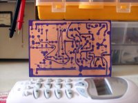
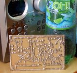
I use to watch schematic and to paint boards using permanent ink pen from U.S. .... and then all wires are converted to copper...just that..then i corrode them using some dark ferric compound and just solder the copper lines...melting solder over them...it is nice and fast... i can glue the board into chassis...nothing need to be inverted or checked into the other board side...
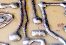
The care we must have is to build from the left to the rigth... because we need room to the soldering iron tip and body to solder... all parts are pré soldered..some solder is melted into the leads..and them is to apply them watching schematic.... super simple.
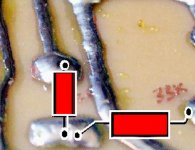
Do not worry about the 33K resistance... this is 33K plus 33K (result 66K)...in series with a third one of 2K i have the 68K Dunlap has asked for his amplifier...i use resistances as jumpers too.
I use to make those boards since 1970...because more simple, easier and faster...and we do not need to think..just copy lines that interconnect parts and ready to go!
regards,
Carlos
I am always searching for something new.
This amplifier is lasting for long...it is really nice.... also because i am waiting the real boards to assemble... after that..for sure i will be buiding other amplifiers.
The boards are reliable, and i use them to other amplifiers too...running wires... p2p and a big mess...i don't care about...my interest... what i want is to listen and to listen as soon as possible...life is short...i want to be happy... this drives me happy..so...let's do more!
This same Dunlap Krill amp board...made for the Krill, will be used into the future to other amplifiers...all them use differential, voltage stages and output...so... other needed things will be p2p... or aerial...or subboards.
I use to watch schematic and to paint boards using permanent ink pen from U.S. .... and then all wires are converted to copper...just that..then i corrode them using some dark ferric compound and just solder the copper lines...melting solder over them...it is nice and fast... i can glue the board into chassis...nothing need to be inverted or checked into the other board side...
The care we must have is to build from the left to the rigth... because we need room to the soldering iron tip and body to solder... all parts are pré soldered..some solder is melted into the leads..and them is to apply them watching schematic.... super simple.
Do not worry about the 33K resistance... this is 33K plus 33K (result 66K)...in series with a third one of 2K i have the 68K Dunlap has asked for his amplifier...i use resistances as jumpers too.
I use to make those boards since 1970...because more simple, easier and faster...and we do not need to think..just copy lines that interconnect parts and ready to go!
regards,
Carlos
Attachments
- Status
- Not open for further replies.
- Home
- Amplifiers
- Solid State
- Krill - The little amp that might...