thank you folks by the understanding, the support and kindness
Sorry to not finish the work i have started..... well.... amplifier is fine despite my health problems.
I hope i will be better in a matter of monthes.
thank you,
regards,
Carlos
Sorry to not finish the work i have started..... well.... amplifier is fine despite my health problems.
I hope i will be better in a matter of monthes.
thank you,
regards,
Carlos
Carlos,
This is no good...... time for some gentle exercise, which should improve things.
I'm very sorry to hear of blood pressure issues. Get well soon,
Hugh
This is no good...... time for some gentle exercise, which should improve things.
I'm very sorry to hear of blood pressure issues. Get well soon,
Hugh
Re: thank you folks by the understanding, the support and kindness
Hello Carlos 😀 😀 😀 😀 I am sending you good thoughts for your health to improve so that you can return to doing those things you enjoy! I know that this is the "hot" season for you so you double need to take things easy and relax with a cold drink and maybe a cold towel on your head. All good things come with time my friend. Last year I had a 5 way heart by-pass, my wife had a stroke, and Manfred the wonder Dachshund ruptured a disk. Now we are all doing very well - so do not despair - keep your spirits and thoughts on positive things. We are all on your side and wishing you the best!!! 😉
destroyer X said:
Sorry to not finish the work i have started..... well.... amplifier is fine despite my health problems.
I hope i will be better in a matter of monthes.
thank you,
regards,
Carlos
Hello Carlos 😀 😀 😀 😀 I am sending you good thoughts for your health to improve so that you can return to doing those things you enjoy! I know that this is the "hot" season for you so you double need to take things easy and relax with a cold drink and maybe a cold towel on your head. All good things come with time my friend. Last year I had a 5 way heart by-pass, my wife had a stroke, and Manfred the wonder Dachshund ruptured a disk. Now we are all doing very well - so do not despair - keep your spirits and thoughts on positive things. We are all on your side and wishing you the best!!! 😉
By DX - Sorry to not finish the work i have started..... well.... amplifier is fine despite my health problems.
Amp is not as important as you are , DIYaudio without the destroyer would not be the same.. get well soon..
OS
Re: Health problems forces me to stop construction...i cannot be sitted for too long
What an odd foot you have Carlos...😀
Take it easy.
destroyer X said:
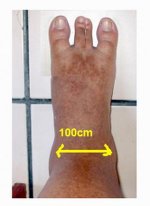
circulation problems...the left foot turns enormous because of return blood circulation damaged...also blood pressure is dangerous.
Sorry folks..will stop for some monthes till the health goes into a better shape.
What an odd foot you have Carlos...😀
Take it easy.
Attachments
Ahahahahah!... it is turning ugly that way.
Circulation problems... return circulation defective goes turning it dark brown.... really ugly...not less ugly than to have three finger.
regards,
Carlos
Circulation problems... return circulation defective goes turning it dark brown.... really ugly...not less ugly than to have three finger.
regards,
Carlos
HEI UNCLE CHARLY !!!!!
may be if you have circulation issues together with high presure you might wana recheck your feedback trace and/or your bias circuits for better idle ....
ALL THE BEST MY FRIEND ....GET VERY WELL SOON !!!!!
may be if you have circulation issues together with high presure you might wana recheck your feedback trace and/or your bias circuits for better idle ....
ALL THE BEST MY FRIEND ....GET VERY WELL SOON !!!!!
Will remove all CCS Sakis, also will remove the voltage stabilizers
I cannot feed my sistem with so big and constant energy anymore... also i will have to increase the load value...not more 4 ohms to me.
No more bootstrapps too.
bye
Carlos
I cannot feed my sistem with so big and constant energy anymore... also i will have to increase the load value...not more 4 ohms to me.
No more bootstrapps too.
bye
Carlos
No one has pointed out any errors now for a few days so I am posting what I believe is the corrected schematic for the 50W amp. I will ask the moderators for help with updating previous posts.
I have made a minor part value change in the caps in the voltage doubler. This is to make the cap fit the board space and will not effect anything else.
In the 50W amp, R60 MUST be set to maximum resistance before the circuit is powered up. The resistance is then reduced until minimum offset is reached on the output. If this trim pot is installed with the value too low it will cause damage to several transistors and resistors.
Attachments
Here is the schematic for the 100W amp.
In this amp, R60 should be set at mid value and adjusted for minimum DC at the base junction of Q7 and Q10. R32 and R33 are set to minimum and only one is adjusted to give minimum offset. Which one is adjusted depends on the polarity of the offset. If one increases the offset, return it to minimum and adjust the other.
On both amps, all adjustments should be checked and corrected after the bias has been set and the amp has stabilized thermally. this will take about 30 minutes.
All of this is done with no input signal and no load on the output.
Attachments
Re: Health problems forces me to stop construction...i cannot be sitted for too long
Hello Carlos
Get better my friend.
Gaetan
destroyer X said:
circulation problems...the left foot turns enormous because of return blood circulation damaged...also blood pressure is dangerous.
Sorry folks..will stop for some monthes till the health goes into a better shape.
bye
Carlos
Hello Carlos
Get better my friend.
Gaetan
Steve, in the 100 watt schematic, C4 is to be connected to the other end of D12. Otherwise, all else looks O.K.
You've mentioned the 'start-up' position of the trimpots (R60) for both versions, but have not mentioned anything about the setting of the preset/trimpot for bias at 'start-up'. By the way, the bias trimpot is not numbered/designated in the 100w schematic. This could lead to confusion later on if ever reference is made to bias setting (components).
You've mentioned the 'start-up' position of the trimpots (R60) for both versions, but have not mentioned anything about the setting of the preset/trimpot for bias at 'start-up'. By the way, the bias trimpot is not numbered/designated in the 100w schematic. This could lead to confusion later on if ever reference is made to bias setting (components).
Samuel Jayaraj said:Steve, in the 100 watt schematic, C4 is to be connected to the other end of D12. Otherwise, all else looks O.K.
You've mentioned the 'start-up' position of the trimpots (R60) for both versions, but have not mentioned anything about the setting of the preset/trimpot for bias at 'start-up'. By the way, the bias trimpot is not numbered/designated in the 100w schematic. This could lead to confusion later on if ever reference is made to bias setting (components).
You are correct about C4. I didn't catch that because I had already corrected it. I accidentally re posted the older schematic again. The new one is attached.
The bias trim pot is R27. It is on the schematic but I have now moved the designator closer to the trimmer to make it more obvious.
The setting of the trim pot for the bias at start up is not critical. The amp cannot be over biased with the voltage drop generated by the 3 diodes. It may run very warm, but no damage will occur. The bias should be set as soon after power up as possible. The actual setting depends somewhat on how much current you feel each output transistor should conduct at idle. As I have stated, I use a distortion meter and set the bias for minimum distortion. This usually results in a dissipation of about 3 to 5W or about 60 to 100mA (per device) for a 50V supply.
Attachments
AKSA said:Carlos,
This is no good...... time for some gentle exercise, which should improve things.
I'm very sorry to hear of blood pressure issues. Get well soon,
Hugh
As Hugh said ... gentle exercise is an excellent idea ... try some Yoga, Pilates, Feldencris, or Alexander Techniques 🙂
please, get well soon
🙂
pcb for 100w
Hi,
I try to draw PCB not so good 😉 http://i43.tinypic.com/i26aee.jpg regards alex mm 😀
Hi,
I try to draw PCB not so good 😉 http://i43.tinypic.com/i26aee.jpg regards alex mm 😀
Alex,
2 things: - how does the diode string contact the heatsink?
- I think the bias transistors are meant to run hot so no need for this heatsink?
Edit: Also have you incorporated pots across R30 & R31?
But looks very compact - well done!
2 things: - how does the diode string contact the heatsink?
- I think the bias transistors are meant to run hot so no need for this heatsink?
Edit: Also have you incorporated pots across R30 & R31?
But looks very compact - well done!
Alex, your attempt at designing a PCB for the 100 watt version is good. Only try to thermally couple Q1 and Q2. In addition, make some provision for caps to shunt both the IN4148 diode stacks in the front end.
jkeny said:Alex,
2 things: - how does the diode string contact the heatsink?
- I think the bias transistors are meant to run hot so no need for this heatsink?
Edit: Also have you incorporated pots across R30 & R31?
But looks very compact - well done!
Nice looking board Alex.
The diode string must contact the heat sink for thermal tracking. The bias transistors will not run hot as there is very little voltage drop across them. The rest of the TO220 transistors are intended to run hot. They will dissipate about 0.5W each with the values shown for the 100W amp.
The output Zobel connects gnd to gnd.
Remove the decoupling from the Signal Ground.
Check polarity of C4.
Remove the decoupling from the Signal Ground.
Check polarity of C4.
- Status
- Not open for further replies.
- Home
- Amplifiers
- Solid State
- Krill - The little amp that might...