There are only 6 natural teachers in this forum
at least those are the ones i could recognize, the ones i could met, the ones i could detect, the ones had intention to teach and made that perfectly.... people that knows how to explain things.
Also the effort we felt from you... addicted to help, to share things, is very nice... very friendly, very cooperative, something that i believe come from a superior soul... a more developed man... those have controled Ego... the ones less selfish than others.
Congratulations Steve...our forum is big, there are monsters in know how, great designers, nice people, but good teachers...natural teachers..only few.
I could be one of those..if i had more knowledge to share...one day i will be, and will teach folks to design amplifiers in a very simple and fast way..alike "design your own amplifier in 5 minutes".. i am still developing the method with my Orkut group...this one, the group, the communitty, is beeing the pilot testing...my teaching laboratory crew.
regards,
Carlos
Steve Dunlap said:Did I scare everyone off with my explanation?
Most likely inspired some to get into the workshop and play around with the circuit. I'm working on plans for my case layout while await the arrival of my new soldering station. 😎
Some folks do not understand how amplifier works.... or how your amplifier operates
I could have many folks buiding mine because mine was a hell simple, a copy of amplifiers made into the seventies, adjusted copy, increased, upgraded and updated.... something very romantic that use to move sensitive people.
The understanding about how my amplifiers works was deeply informed, each resistance function, each transistor function, each circuit function.... this understanding made them trust, because if something result strange they had the "tools" to debug.
In my imagination, having not deep understanding reduces the confidence to assemble.... and each one of the interested ones will be waiting someone to assemble first (I did it... and i cannot understand why they continue scared).... the problem is that all them waiting the first one to assemble...this results no one moves.
You gonna see, after the first one build (do not know why they did not have trust on me...i have built!) others will follow that first one.
In my country we call this "Boi de Piranha"...... a bull is sacrificed when people has to cross rivers that has too much Piranha fix..... they select an old bull or cow and produce some cuts to force the animal to bleed..... then this animal is pulled using ropes to cross... the blood attract Piranha fishes that start to attack.... because of blood smell and vibrations into the watter, the hell piranha fishes goes to the bull.... they can transform and entire bull in bones after 5 minutes...only bones rest in the river bottom....but WHILE this sacrificed animal is beeing eated, the main group of cows and bulls cross the river in a very safe way.
So.... people afraigthned will wait someone to take the risk first.
Interesting...i did it..but maybe happened into the other thread and this had lost strength.
It is difficult...i have offered boards into group buy, was the second amplifier published...hundreds have assembled the first one (The standard)... even this way, having boards offered into group buy, not more than 100 boards were sold.... was the cost price, non profit......and some of those folks have not already assembled boards that still laying down over their benches.... i have worked hard and daily.... thousands of texts made, more than 200 pages.... more than 1 years...and the result was very small.... so...be patient.... you have a long run in the front of you...but this use to be very pleasant too.
It is time to seed.
regards,
Carlos
Super detailed circuit description helps
each resistance function, the flow of current, charts with voltage and charts with current, SPECIFICATIONS...people loves numbers of THD and pictures...macro pictures from your circuit assembled...the one you have.... close ups.
Circuit description.. this helps when we want folks to be interested and to build our amplifiers.
They must see to feel interested.. schematic do not helps.... real thing is stronger.
Carlos
No ,c2c was right.. now we play with boosted bias diamondDid I scare everyone off with my explanation?
buffer's and the lot... It seems the diamond is used in a lot of headphone amp designs (millet, etc.) yours is one of the
few to use it in a OP stage. NOT scared of the krill (sounds
like a monster 😀 )
OS
http://www.triadaudio.net/Triad_Audio/Downloads_files/Ultra%20%20Biasing%20Boost%20with%20Enhanced%20Current%20Mirrors.pdf
Try this as a OP stage..
Hi Steve,
really like the design 🙂
But aren't D12 and D22 the wrong way around in the diagrams?
I also wondered if there was any advantage in replacing the 3 bias chain diodes with a vbe multiplier ?
My thought was it would be less sensitive to changes in current through the bias chain?
really like the design 🙂
But aren't D12 and D22 the wrong way around in the diagrams?
I also wondered if there was any advantage in replacing the 3 bias chain diodes with a vbe multiplier ?
My thought was it would be less sensitive to changes in current through the bias chain?
Thanks Carlos. I appreciate the support.
"In my country we call this "Boi de Piranha"...... a bull is sacrificed when people has to cross rivers that has too much Piranha fix..... they select an old bull or cow and produce some cuts to force the animal to bleed..... then this animal is pulled using ropes to cross... the blood attract Piranha fishes that start to attack.... because of blood smell and vibrations into the watter, the hell piranha fishes goes to the bull.... they can transform and entire bull in bones after 5 minutes...only bones rest in the river bottom....but WHILE this sacrificed animal is beeing eated, the main group of cows and bulls cross the river in a very safe way."
In my country we use bridges or boats. Of course we don't have piranha.
ostripper said:
No ,c2c was right.. now we play with boosted bias diamond
buffer's and the lot... It seems the diamond is used in a lot of headphone amp designs (millet, etc.) yours is one of the
few to use it in a OP stage. NOT scared of the krill (sounds
like a monster 😀 )
OS
http://www.triadaudio.net/Triad_Audio/Downloads_files/Ultra%20%20Biasing%20Boost%20with%20Enhanced%20Current%20Mirrors.pdf
Try this as a OP stage..
I have seen the diamond buffer used in a number of amps as an input/driver stage. I find this to generate much useless heat. The heat produced when used as a headphone amp is manageable. The diamond buffer was also used as (are you ready for this?) a BUFFER by at least one large semiconductor company.
Symon said:Hi Steve,
really like the design 🙂
But aren't D12 and D22 the wrong way around in the diagrams?
I also wondered if there was any advantage in replacing the 3 bias chain diodes with a vbe multiplier ?
My thought was it would be less sensitive to changes in current through the bias chain?
You are correct. D12 and D22 are shown backwards. D20 is also backwards. They are correct on the boards.
The changes in current in the bias diode chain is very small and does not produce a significant voltage change. The current here is less than 0.1mA and the change is that divided by the gain of the bias transistors. The change is also a reduction in current and I'm not sure the voltage drop on these diodes can go lower.
Any method of producing the desired voltage difference between the bases if the bias transistors will work here. Remember that the diode string does the thermal tracking, so if you replace it, you will need another method of doing that. A vbe multiplier should work if the transistor is mounted to the heat sink.
c2cthomas said:
Most likely inspired some to get into the workshop and play around with the circuit. I'm working on plans for my case layout while await the arrival of my new soldering station. 😎
It seems that c2cthomas may have volunteered to build some cases for a case building thread. I think that since he will do the work as well as document it and post pictures, I will let that be his thread. I will give pointers as or if needed.
The changes in current in the bias diode chain is very small and does not produce a significant voltage change. The current here is less than 0.1mA and the change is that divided by the gain of the bias transistors. The change is also a reduction in current and I'm not sure the voltage drop on these diodes can go lower.
The reason I suggested a vbe multipler is because 2 of your diode are shunted by a resistor, and while it's voltage drop is less than that of the 2 diodes the variation is directly proportional to change in current. I also wonder how effective these shunted diodes are at thermal compensation ?
Having said that, if what you have works well enough stay with it 🙂
Symon said:
The reason I suggested a vbe multipler is because 2 of your diode are shunted by a resistor, and while it's voltage drop is less than that of the 2 diodes the variation is directly proportional to change in current. I also wonder how effective these shunted diodes are at thermal compensation ?
Having said that, if what you have works well enough stay with it 🙂
The resistor is so the bias can be adjusted. The diodes parallel with it set the maximum voltage drop in the event of an open wiper contact and the resistor sets the minimum. As I explained in my previous post, the current change in the string is very small and would show up as a maximum voltage change of less than 0.01V at the maximum resistor setting. Since I am looking for a voltage drop of approximately 0.7V this represents a worst case of less than 1.5% voltage change. I am willing to live with that.
The thermal tracking is very good with this method. Remember, one diode is not bypassed.
Steve,
We WILL have a forum for construction techniques soon so you could make a new thread in SS amps and we could transfer it when the forum appears!

Mark
We WILL have a forum for construction techniques soon so you could make a new thread in SS amps and we could transfer it when the forum appears!
Mark
Have gotten very interested in this, especially the 100W version as it would fit my needs exactly 🙂
One thing I did notice though, on the 50W schematic in Post #326, the power supply shown is dangerously wrong! While I realise that those who have been reading the thread will know this, you never know who might just jump in, give it a go - and kill themselves
I'm also puzzled by the frontend power supply. I realise it's a voltage doubler, but when I simulated it in LTSpice as shown (with the diodes in the -ve half corrected), the startup time is huge. The 10K resistors seem to be the cause and when lowered to 100 ohm, the startup is more correct, but still quite long, about 5 seconds before the output comes up to voltage.
I realise the zeners are only 33v here, but thats because I cant find a 55V zener SPICE model yet, or a good 27v one.
Attachments

jaycee said:
One thing I did notice though, on the 50W schematic in Post #326, the power supply shown is dangerously wrong!
I'm also puzzled by the frontend power supply. I realise it's a voltage doubler, but when I simulated it in LTSpice as shown (with the diodes in the -ve half corrected), the startup time is huge. The 10K resistors seem to be the cause and when lowered to 100 ohm, the startup is more correct, but still quite long, about 5 seconds before the output comes up to voltage.
I realise the zeners are only 33v here, but thats because I cant find a 55V zener SPICE model yet, or a good 27v one.
This mistake was spotted earlier on and corrected in post #281 and the PS in post #327 looks to be ok too - so take a look there. This is still a work in progress and catching mistakes such as this is appreciated by all of us - so keep posting your findings and suggestions!
I don't know the answer to your question about the LTSpice simulations - but I'm sure that Steve will be around to comment.
ps - Luv your redraw of the PS - very nice!
OK, I guess the 50W amp is just the 100W with some different parts after all 🙂
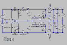
I couldn't help my noodling around in LTSpice, and this popped out - it's a similar method based around the Cockroft-Walton multiplier. It seems to have a faster startup time.
The silly stack of zener diodes is me trying to get near to 55V with the zener models that LTSpice has - a 33V, a 15V and an 8.2V!
Capacitors C1 and C3 would need 100V rating, C2 and C4 160V rating. The MURS120 diodes again were just a model chosen, 1N4004 or even 1N5404 would be plenty.
The FJP1943/5200 are 80W 30MHz transistors from Fairchild, based on their 2SA1943/2SC5200 clones, in TO-220 format.
The resistors on the output are just for load tests - they cause about 120mA to be drawn - more than enough for 2 frontends.
I hope this turns out to be useful 🙂 I have always thought about regulated frontend, but haven't been keen on having to have a custom transformer wound to put out slightly higher voltages for it. The doubler circuit solves this quite nicely though.
Attachments
Hi jaycee! From your profile "Blowing Electronics up, Burning things with soldering irons 🙂" Ahh yessss! I've been doing such for many years now - and hopefully for many more to come.
Nice work on the PS! Between your suggestions and ostripper I keep getting the urge to breadboard out an entirely different amp! I already have my monoblock PWB's from Steve tho - so for now I'll stick with getting the 50W mono's done 1st. 😉
Nice work on the PS! Between your suggestions and ostripper I keep getting the urge to breadboard out an entirely different amp! I already have my monoblock PWB's from Steve tho - so for now I'll stick with getting the 50W mono's done 1st. 😉
Variac said:Steve,
We WILL have a forum for construction techniques soon so you could make a new thread in SS amps and we could transfer it when the forum appears!
Mark
Hi Variac. That's good to hear. I guess I need to order some aluminum now.
jaycee said:Have gotten very interested in this, especially the 100W version as it would fit my needs exactly 🙂
One thing I did notice though, on the 50W schematic in Post #326, the power supply shown is dangerously wrong! While I realise that those who have been reading the thread will know this, you never know who might just jump in, give it a go - and kill themselves
I'm also puzzled by the frontend power supply. I realise it's a voltage doubler, but when I simulated it in LTSpice as shown (with the diodes in the -ve half corrected), the startup time is huge. The 10K resistors seem to be the cause and when lowered to 100 ohm, the startup is more correct, but still quite long, about 5 seconds before the output comes up to voltage.
I realise the zeners are only 33v here, but thats because I cant find a 55V zener SPICE model yet, or a good 27v one.
Those are suppose to be 10 ohm 5W resistors. That should help with the start up time.
- Status
- Not open for further replies.
- Home
- Amplifiers
- Solid State
- Krill - The little amp that might...