Unless this is a really bad audio interface, but for the purpose of time reference basically any audio interface will be fine.Audio Interface.
ex. the excellent id24 that fluid just purchased:
Distortion isn't important for referencing time btw.
There is an argument to be made for the mic preamp. That's why I was asking which one you were talking about.
But in most cases the low pass /high pass filters are far enough to not have any significant issues.
Edit: I just realized this last part isn't true.
As soon as the signal out of the amplifier is time synced, all other things are the same in a relative way.
Unless the mic preamp contains a ADC/DSP or so.
In a multi-mic solution, it does bring up the importance of close matching of the microphones.
Or at least within the frequency range we are interested in.
Otherwise there will be time/latency = phase differences between them.
Obviously this can be easily compensated for with a simple calibration process.
So I guess they don't have to be matched SO closely.
Last edited:
Please try using the mataa_measure_signal_response(...) function for audio I/O instead of the mataa_measure_IR(...) so you can take a look at the data you get from the microphone and from the loopback channel. Check for things like clipping or cutoff at the beginning or end of the signals, or other undesired effects.
Here it is:

There is some kind of mean drift and a (little) spike at the end.
I also implemented a 'phase controlled exponential chirp' from https://www.uni-weimar.de/kunst-und...ation_of_ESS_impulse_response_measurement.pdf

The peak at the end is gone, but the mean drift is still present and also the preringing (not shown).

So, putting the samplerate at 192kHz iso 44.1kHz solved the problem. I don't know why, but will simply use 192kHz.

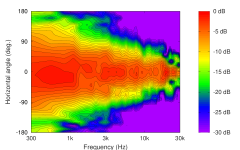
I measured my Elac Debut 2.0 from 0 to 180 degrees in 1 degree steps (still with my crappy test setup). I seriously doubt whether the 2D modal fitting and reevaluation is worth it once you have the measurement process automated. Get yourselves a cup of coffee and its done.
I measured with Octave, saved the impulse response to a wav file, read that into REW (see image above), applied a window too all* measurements and exported FRD data for use in VituixCad:
.png")
* I only could load ~120 measurements into REW before I ran out of memory.
I measured my Elac Debut 2.0 from 0 to 180 degrees in 1 degree steps (still with my crappy test setup). I seriously doubt whether the 2D modal fitting and reevaluation is worth it once you have the measurement process automated. Get yourselves a cup of coffee and its done.
I measured with Octave, saved the impulse response to a wav file, read that into REW (see image above), applied a window too all* measurements and exported FRD data for use in VituixCad:
* I only could load ~120 measurements into REW before I ran out of memory.
It's easy to forget.* I only could load ~120 measurements into REW before I ran out of memory.
Thanks for the paper Tom. Number one problem of the fast signals is that there is little energy below 300 hertz. Rise time of the drivers is fast enough, but there is a delay in the time of the system. And there is an inherent lesser efficiency in the lower frequencies to test in the first place. Add in a port and you have another layer of trouble in getting a good signal to your microphone.
Mark
Both the drift and the spike at the end looks wrong. Do you have a filter somewhere? Also, the loudspeaker signal looks like it has not fully died off to zero when the recording stopped.Here it is:
View attachment 1286667
There is some kind of mean drift and a (little) spike at the end.
Ok, that smells like some anti-aliasing somehow.So, putting the samplerate at 192kHz iso 44.1kHz solved the problem. I don't know why, but will simply use 192kHz.
That's all pretty nice!I measured my Elac Debut 2.0 from 0 to 180 degrees in 1 degree steps (still with my crappy test setup). I seriously doubt whether the 2D modal fitting and reevaluation is worth it once you have the measurement process automated. Get yourselves a cup of coffee and its done.
I measured with Octave, saved the impulse response to a wav file, read that into REW (see image above), applied a window too all* measurements and exported FRD data for use in VituixCad:
* I only could load ~120 measurements into REW before I ran out of memory.
.png")
But I wonder:
- Why do you export the data to REW to apply a time window and then export to VituixCad for plotting? You can do all of this right in Octave, fully automated. I attached an example I did in Octave a while back with the OSMC. Once you're done with the coffee, the plot shows up on your screen with not extra work.
- Did you export the full impulse response data? 180 x 1.3 seconds at 192 kHz is quite a bit of data! Cropping the data before to the relevant 3 ms before exporting would reduce the size of the dataset by about 500x.
Attachments
Both the drift and the spike at the end looks wrong. Do you have a filter somewhere? Also, the loudspeaker signal looks like it has not fully died off to zero when the recording stopped.
I didn't deliberately put a filter somewhere. My room is far from anechoic...
One step at a time...But I wonder:
- Why do you export the data to REW to apply a time window and then export to VituixCad for plotting? You can do all of this right in Octave, fully automated. I attached an example I did in Octave a while back with the OSMC. Once you're done with the coffee, the plot shows up on your screen with not extra work.

I think its time to shift the focus. I see 2 possibilities for the next steps.
1) Create a gui
2) Moving mic as a step towards 3D
Anyone any ideas about the GUI framework? What the GUI should look like? ...?
Anyone any ideas about the 'moving mic' hardware?
Both are not really my forte, so feel free to take the lead ;-)
1) Create a gui
2) Moving mic as a step towards 3D
Anyone any ideas about the GUI framework? What the GUI should look like? ...?
Anyone any ideas about the 'moving mic' hardware?
Both are not really my forte, so feel free to take the lead ;-)
As I understand it, we want the microphone moving in 3D to do what the Klippel system does. So we need to move the microphone in 3D.
I personally don't see why a GUI would be needed to scan the soundfield by moving the microphone around the speaker. I even think a GUI might interfere with the program. If at some point you absolutely want a GUI, I'd suggest you look at the cross-plaform GUI toolkits so it would work on most computer platforms. However, a warning is in order: it's quite difficult to make good GUIs!
I personally don't see why a GUI would be needed to scan the soundfield by moving the microphone around the speaker. I even think a GUI might interfere with the program. If at some point you absolutely want a GUI, I'd suggest you look at the cross-plaform GUI toolkits so it would work on most computer platforms. However, a warning is in order: it's quite difficult to make good GUIs!
I've caught up with this thread recently and coincidentally ran across this video that may be of interest. As far as moving-and-placing the mic, it's not "exactly what Klippel does" but it may be an improvement.
I came across an interesting video using pvc tubes and 3D printed parts for a motion system.
The camera motion system videos are a gold mine. I think I need to spent some more time on youtube...
As I understand the thread so far. 1 automated rotational axis, 1 automated linear axis for height and 1 manually adjusted axis for distance from rotational axis?
What would the needed accuracies be angular and height, and what time could be allotted for the system to stabilize after motion?
Would people be comfortable with permanent mounting holes or fixtures in their roof?
What would the needed accuracies be angular and height, and what time could be allotted for the system to stabilize after motion?
Would people be comfortable with permanent mounting holes or fixtures in their roof?
I guess if you ask 10 people you get 10 answer (or more). I would like to have the radial distance motorized. The top and bottom of the cylinder also needs to be measured. I think I remember an accuracy of 5mm. For me, permanent mounting holes in my roof would not be my first choice.
OK, roof hanging would be easier.
So say +/- 1 degree rotational, +/- 1 mm on height and radial distance. What would the needed movement envelope be? Max/Min distance from DUT? Max dimensions and weight of DUT?
So say +/- 1 degree rotational, +/- 1 mm on height and radial distance. What would the needed movement envelope be? Max/Min distance from DUT? Max dimensions and weight of DUT?
Actually more like +/- 0.1 to 0.05 degree rotational accuracy depending on what center distance is needed.
Reference again:I guess if you ask 10 people you get 10 answer (or more). I would like to have the radial distance motorized. The top and bottom of the cylinder also needs to be measured. I think I remember an accuracy of 5mm. For me, permanent mounting holes in my roof would not be my first choice.
I could see 2 parallel beams above (height adjustable to the height of the room) with 2 vertical support strut’s on each side (with some cross-supports) of the testing area holding-up those beams. The beams would support a drop-down center spindle for the rotational axis and the vertical and inward/outward axis’s would hang down from the rotational axis’s base. It shouldn’t be to much bulk other than achieving stiffness considering that the motors aren’t that heavy.
ex. sort of with the dude hanging being the moving-parts (rotational axis base and the other 2 axis’s):
https://www.baseblocks.fit/pages/b-...MI8daBl7z_hAMVMnF_AB2vCwhxEAQYAyABEgLBCfD_BwE
..yes, the parallel beams would have to be slightly longer than twice the desired length of the inward/outward axis-arm; so if you want 4 feet as with the Klippel setup above you would need just over 8 feet in length.
Last edited:
I could watch these moving arms all day long... fascinating stuff!
If/when someone is going to build such a thing, consider the option to use multiple microphones, so different positions could be measured in one step (different angles, different distances).
If/when someone is going to build such a thing, consider the option to use multiple microphones, so different positions could be measured in one step (different angles, different distances).
pickup any CNC or 3d printer stepper motor kit 🙂Anyone any ideas about the 'moving mic' hardware?
as well as search for arduino/esp32/stm32/rp2040/raspberry pi stepper motor on your favorite search engine.
Here's the best picture that I have been able to find.
https://www.klippel.de/fileadmin/user_upload/NFS_1.0.7_StudioMonitor.png

https://www.vevor.ca/drawer-slide-c...l-bearing-full-extension-500lb-p_010873950531

60 inch drawer slides. Reasonably priced. You can us these for vertical and horizontal movements. 2 pair would be enough for horizontal and vertical movement of the microphones. And provide a fair degree of built in rigidity.

A little perspective on the size of these. They are more than adequate for the task at hand.
I'll try and put together a list of parts and places to order as I cobble together something for myself.
Kitchen is finally installed:

Mark
https://www.klippel.de/fileadmin/user_upload/NFS_1.0.7_StudioMonitor.png
https://www.vevor.ca/drawer-slide-c...l-bearing-full-extension-500lb-p_010873950531
60 inch drawer slides. Reasonably priced. You can us these for vertical and horizontal movements. 2 pair would be enough for horizontal and vertical movement of the microphones. And provide a fair degree of built in rigidity.
A little perspective on the size of these. They are more than adequate for the task at hand.
I'll try and put together a list of parts and places to order as I cobble together something for myself.
Kitchen is finally installed:
Mark
Last edited:
Klippel manual gives physical dimensions to the system for our reference.
https://www.klippel.de/fileadmin/kl...D_System/PDF/C8 Near Field Scanner System.pdf
Page 8
https://www.klippel.de/fileadmin/kl...D_System/PDF/C8 Near Field Scanner System.pdf
Page 8
Attachments
- Home
- Design & Build
- Software Tools
- Klippel Near Field Scanner on a Shoestring