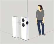
Here is a Sketchup screenshot of a mockup of a 5.5" coax with 4 6.5" woofers, the new MISCO XBL2 devices which have enough displacement for -3db at 30 Hz at 105 db in half space. The box is the same size as the LS60, except 50 mm wider. At that width there is barely a 1 mm gap between the horizontally opposed woofers so it needs to be a tad wider. It does loom wider than the LS60 but I doubt that matters much in a furnished living room. The benefit of the larger size is 54 L of internal volume. If just 40L of that is used for the woofers, it takes less than 50W to reach Xmax. The much smaller volume allocated in the LS60 is the reason it needs so much more power.
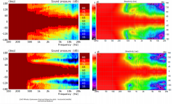
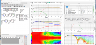
I did a Vituix sim with mirror equalized crossover and diffraction tool generated directivity for the woofers. I used the Klippel NFS directivity from the ASR Kef R3 review for the coax. I then compared the simulated polar maps with those in the LS60 white paper. Finally, a Vituix screenshot.
This design, as does most using the R3 directivity, achieves a 9.6 predicted preference rating out of a possible 10. It seems R3 layout, W-Coax_W, WWCWW, are more about maximizing woofer displacement than anything else. 4 of the Misco 6.5s which have 10 mm xmax seems enough for home use sealed. I experimented with modelling a rear woofer/rear resistance vent and that can yield a cardioid like response for little extra complexity.
Attachments

I agree. That is why I said it had to be a tad wider. If you look at the step file, you can see the details. They've added a cover for the polar vent to shape/direct the air flow to the sides. It seems to me with these you would only need about a 10 mm gap.
Depending on what cad tools you have, the step file isn't so easy to look at. I managed to convert to STL and then import it into sketchup but even zipped the file is too large to attach.
Depending on what cad tools you have, the step file isn't so easy to look at. I managed to convert to STL and then import it into sketchup but even zipped the file is too large to attach.
Attachments

Nice modelling nc535.
I did some brief modelling too, and can confirm that if one wants to maintain the svelte proportions of the ls60
ie. narrow just enough for the midrange/coaxial @ 130mm width, side mounded woofers results in a loss of about about 4.5dB below 300Hz, compared to infinite baffle. The other side of the coin of this, is that one can look at the 2pi response and it will be only a 0.5dB to 1 dB off.

If one applies the baffle diffraction signature of side mounted 5.25" woofers, to hit the maximum SPL target of 106dB@100Hz, 100dB@50Hz and 84dB@20Hz, so far the most suitable woofer for the job is the ES140TiA-8, as long the foam plug on the vented pole piece does it's job. 4 of them have enough volume displacement to hit those targets in 12.5L, and they are 67mm deep:

Everything else is too wide eg. E150HE-44, DIYSG 558, Misco 6.5" XBL for back to back mounting in 130mm.
If one was happy to increase the cabinet width to 180-190mm; that opens up options to many other choices, too, instance the venerable old RS225-8 (has fake vented pole piece)?
And then, should a driver then even need to be side mounted? 6.5" driver can be crammed into a 190mm wide front baffles...
I did some brief modelling too, and can confirm that if one wants to maintain the svelte proportions of the ls60
ie. narrow just enough for the midrange/coaxial @ 130mm width, side mounded woofers results in a loss of about about 4.5dB below 300Hz, compared to infinite baffle. The other side of the coin of this, is that one can look at the 2pi response and it will be only a 0.5dB to 1 dB off.
If one applies the baffle diffraction signature of side mounted 5.25" woofers, to hit the maximum SPL target of 106dB@100Hz, 100dB@50Hz and 84dB@20Hz, so far the most suitable woofer for the job is the ES140TiA-8, as long the foam plug on the vented pole piece does it's job. 4 of them have enough volume displacement to hit those targets in 12.5L, and they are 67mm deep:
Everything else is too wide eg. E150HE-44, DIYSG 558, Misco 6.5" XBL for back to back mounting in 130mm.
If one was happy to increase the cabinet width to 180-190mm; that opens up options to many other choices, too, instance the venerable old RS225-8 (has fake vented pole piece)?
And then, should a driver then even need to be side mounted? 6.5" driver can be crammed into a 190mm wide front baffles...
Last edited:
How did you get a STEP file of that woofer? Or did you idea that yourself? Nice work if you did. I would be interested in getting a copy, will PM you.I agree. That is why I said it had to be a tad wider. If you look at the step file, you can see the details. They've added a cover for the polar vent to shape/direct the air flow to the sides. It seems to me with these you would only need about a 10 mm gap.
Depending on what cad tools you have, the step file isn't so easy to look at. I managed to convert to STL and then import it into sketchup but even zipped the file is too large to attach.
Hi all, i like the design very much - but like many others i don't like the price of the speaker pair.
I will wait until the components appear here as spare parts:
KEF spare parts in France
The actual DIY best buy is this here

If there is no problem to get the copper color instead of black - see the price difference!
I will wait until the components appear here as spare parts:
KEF spare parts in France
The actual DIY best buy is this here
If there is no problem to get the copper color instead of black - see the price difference!
Last edited by a moderator:
@tktran303 What would measurements for Vituixcad look like for 4 woofers around coax - Blade configuration ?
"And then, should a driver then even need to be side mounted? 6.5" driver can be crammed into a 190mm wide front baffles..."
Would it be LS60 clone then? You would loose force-cancellation and clean looking front baffle
Also you would loose 2dB of baffle gain https://www.diyaudio.com/community/...r-that-i-would-buy.386203/page-3#post-7022420
HypexFA 3-way dsp-amps are excellent choice for this kind of actives. Just connect them to your favourite media player!
should a driver then even need to be side mounted?
Reaction cancelation is key to this box. You are completely missing the point.
On the sides is all that makes sense, no BS at the frequencies involved, and at those frequencies the 4 woofers are acting as ome and are omnidirectional. Put them anywhere but the sides you get the bipole dip.
dave
I'm talking Canadian Dollars.https://www.shop.ca.kef.com/Where did you get this number from ?
I'm seeing them at 6600€/pair.
Not saying it's cheap but it is considerable less money than 10k€.
$10k CAD (=7,747.97USD=7,446.4euro=6,322.67GBP), i looked yesterday. Summer expected for the blue ones if you pre-order.
dave
dave
you can download from their website...How did you get a STEP file of that woofer? Or did you idea that yourself? Nice work if you did. I would be interested in getting a copy, will PM you.
Reaction cancelation is key to this box. You are completely missing the point.
On the sides is all that makes sense, no BS at the frequencies involved, and at those frequencies the 4 woofers are acting as ome and are omnidirectional. Put them anywhere but the sides you get the bipole dip.
dave
With the drivers mounted on the front and back, provided they are crossed over low enough, any interference due to path diffences should be pretty much eliminated. And then you can shift this up in frequency by keeping box dimensions as small as possible.
Is that all???? do they sell the grill that hides the copper for less than 100e? 🙂Hi all, i like the design very much - but like many others i don't like the price of the speaker pair.
I will wait until the components appear here as spare parts:
KEF spare parts in France
The actual DIY best buy is this here
View attachment 1054766
If there is no problem to get the copper color instead of black - see the price difference!
With the drivers mounted on the front and back, provided they are crossed over low enough, any interference due to path diffences should be pretty much eliminated. And then you can shift this up in frequency by keeping box dimensions as small as possible.
Unfortunatatly the bipole dip from front/back interference happens below the point at which you would choose the XO if you use that to deal with 2πto π transition.
Been there, done that, now i will side mount them.
dave
Dave,
based on your experience, At what frequency did you notice the transition from omnipolar to bipolar in your cabinets?
Our fellow DIYer tested this empirically recently, and found it to be around 100Hz when it starts to deviate significantly.
http://www.htguide.com/forum/showth...tander-designs&p=639917&viewfull=1#post639917
In case that image is lost I will paste below:

No cone driver is perfectly omnidirectional to the observer/measurement device simply due to the difference in path distances When the speaker is rotated and becomes further away from there observation point. But
if we define acceptable omni-polar behaviour as a point where the sound pressure level drops by about 6 dB below the reference axis, it is probably somewhere between 100-150Hz.
it depends on the actual depth of the cabinet which results in larger/smaller path difference when measuring/observing at 90 degrees or 180 degrees.
For the purpose of the dual opposed side firing we need to look at the behaviour at 90°, because now at 180° there is another driver that will give equal output.
because of KEF’s desire to maintain a slim cabinet, they have to use even a smaller coaxial than their usual 5.25” device. But that increases non-linear distortion at higher SPLs, as the driver approaches the limits of its excursion.
So KEF had to increase the excursion of its coaxial. Like all good white papers they’ve tried their best to focus on the positives and explain their position/design goal, and not spend too much time mentioning the negatives (eg. the MF cone, which now acts as a waveguide for the coaxially mounted tweeter moves further in and out and then it will modulate the HF’s treble output, compared to when it is stationary)
but it something of a compromise that KEF has willing to accept. To minimise cone movement they had to choose a reasonable LF/MF crossover point. And in this case chose 390Hz.
The Polar graph on the last page of the white paper you’ll note that shows that up to about 400 Hz, there is good dispersion out to 180 degrees. Note out the red covers 10dB; whilst others cover 5dB range?
Look at 390Hz: they are willing to accept consider a loss of 5-10dB at their crossover point.

well, Never mind just a minor bipolar affect, just orthogonal. 😜
based on your experience, At what frequency did you notice the transition from omnipolar to bipolar in your cabinets?
Our fellow DIYer tested this empirically recently, and found it to be around 100Hz when it starts to deviate significantly.
http://www.htguide.com/forum/showth...tander-designs&p=639917&viewfull=1#post639917
In case that image is lost I will paste below:
No cone driver is perfectly omnidirectional to the observer/measurement device simply due to the difference in path distances When the speaker is rotated and becomes further away from there observation point. But
if we define acceptable omni-polar behaviour as a point where the sound pressure level drops by about 6 dB below the reference axis, it is probably somewhere between 100-150Hz.
it depends on the actual depth of the cabinet which results in larger/smaller path difference when measuring/observing at 90 degrees or 180 degrees.
For the purpose of the dual opposed side firing we need to look at the behaviour at 90°, because now at 180° there is another driver that will give equal output.
because of KEF’s desire to maintain a slim cabinet, they have to use even a smaller coaxial than their usual 5.25” device. But that increases non-linear distortion at higher SPLs, as the driver approaches the limits of its excursion.
So KEF had to increase the excursion of its coaxial. Like all good white papers they’ve tried their best to focus on the positives and explain their position/design goal, and not spend too much time mentioning the negatives (eg. the MF cone, which now acts as a waveguide for the coaxially mounted tweeter moves further in and out and then it will modulate the HF’s treble output, compared to when it is stationary)
but it something of a compromise that KEF has willing to accept. To minimise cone movement they had to choose a reasonable LF/MF crossover point. And in this case chose 390Hz.
The Polar graph on the last page of the white paper you’ll note that shows that up to about 400 Hz, there is good dispersion out to 180 degrees. Note out the red covers 10dB; whilst others cover 5dB range?
Look at 390Hz: they are willing to accept consider a loss of 5-10dB at their crossover point.
well, Never mind just a minor bipolar affect, just orthogonal. 😜
Here are some quick simulations I made for an ASR thread question about side mounting. These are for a 15" driver but the theory holds in principle just the frequency point where the same effect will be seen is different. The side mounting changes how the speaker radiates into the room, there is about a 3dB difference between the sound radiated to the side and what is measured at the 0 axis at around 150Hz. Above that the directivity of the driver causes the difference to increase and the DI to become negative. A smaller driver would have this occur at a higher frequency and should be considered as part of the design to match with the crossover frequency. A blade style woofer mounting would probably benefit from more distance to the wall behind it and having less things placed in between the speakers for the energy directed that way to reflect off. For passive speakers it also creates a pretty good baffle step equalizer with no parts.
In the KEF graph you can see the same pattern, there is quite a lot of energy in the 90 to 120 degree off axis position between 500Hz and 1K.
Forward Mounted

Side Mounted

In the KEF graph you can see the same pattern, there is quite a lot of energy in the 90 to 120 degree off axis position between 500Hz and 1K.
Forward Mounted
Side Mounted
Dave,
based on your experience, At what frequency did you notice the transition from omnipolar to bipolar in your cabinets?
In Tysen with thw W14 somewhere above 450 Hz.
dave
- Home
- Loudspeakers
- Multi-Way
- KEF LS60 Wireless - Finally! a buzzword compliant wireless speaker that I would buy