...
There is also the KSC2690A and KSA1220A.
Just noticed the KSC2690AYS and KSA1220AYS are available again.
160V VCE and hFe > 160 up to 320
Maybe not ideal for an amp running with +/- 80V rails ...
The Unisonic from profusionplc are OK and the tested values look good.
Unfortunatedly the better (higher hFe) 2SA1837LB-TF3T are unavailable. Only the 2SA1837L-TF3T are in stock.
The 2SC4793LB-TF3T are still available.
BR, Toni
P.S.: I have > 2k of the original Toshiba's 😎 And many original 2SK170 ...
The pdf is correct, the LTSpice schematic has a mistake, it says PN5769..
Also, what is special about the PN2369A?
Also, what is special about the PN2369A?
Just high Ft. I chose that transistor 10 years ago, as with most of this design, so don't go reading too much into it. A 2N3906 would probably do fine.
Do you have a capacitor in mind 10000uf/100v are quite large...the boards will be quite large/ more expensive , horizontally mounted only I assume .
The PSU simulation indicates that we need all of this capacitance to provide 300w into 8ohms. Yes, they are large and expensive. Probably the single greatest cost of the amp besides chassis are the bulk caps.
I am looking at a footprint of 40mm dia x 80mm tall snap-in 10,000uF 100v. These are about $11 to $15 ea depending on model. Exact model still TBD to optimize the best ripple current rating.
If we go with flying leads, a single amp board can sit on the amp floor and MOSFETs mounted on vertical heatsink side. If you wanted a stereo amp, you could put the two amp boards on the heatsink and use direct mounting or flying leads. The two trafos could sit side by side in the chassis middle. It’s flexible.
on-board DC protect solid state relay
What devices did you use for the relay?
The DC protect circuit follows this circuit:
Ready-to-Run (RTR) SSR DC Speaker Protection and Delay GB
But with a replacement of the MOSFET by an On Semi TO220 with 250v and 84A capability and 17.5mOhm RDSon. It will use a zener reference and pass transistor to generate 15v
SSR power supply from the 70v rail
Ready-to-Run (RTR) SSR DC Speaker Protection and Delay GB
But with a replacement of the MOSFET by an On Semi TO220 with 250v and 84A capability and 17.5mOhm RDSon. It will use a zener reference and pass transistor to generate 15v
SSR power supply from the 70v rail
Just noticed the KSC2690AYS and KSA1220AYS are available again.
160V VCE and hFe > 160 up to 320
Maybe not ideal for an amp running with +/- 80V rails ...
The Unisonic from profusionplc are OK and the tested values look good.
Unfortunatedly the better (higher hFe) 2SA1837LB-TF3T are unavailable. Only the 2SA1837L-TF3T are in stock.
The 2SC4793LB-TF3T are still available.
BR, Toni
P.S.: I have > 2k of the original Toshiba's 😎 And many original 2SK170 ...
[UP.S.: I have > 2k of the original Toshiba's And many original 2SK170/U]!!!
Really a lot!
We are doing due dilligence with going through the schematics with a fine tooth comb and JPS64 is refining the layout based on these reviews. We are basically waiting for the layouts to be completed though by JPS64.
Prototype Layout Ready for Manufacturing
It's been a while since we have posted an update on this thread, much of it due to everyone's busy schedules and the vastness of this project - requiring a large amount of time to review schematics and double check interfaces, connections, etc. I think we are finally at prototype manufacturing stage though. Here are the schematics for the MainBoard(MB) and the FrontEnd(FE), and various renders of the PCBs and assembled PCBs.
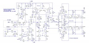
Here is the simplified LTspice Schematic used for the simulation:

The detailed schematics corresponding to the manufactured PCBs are in the PDF's below.
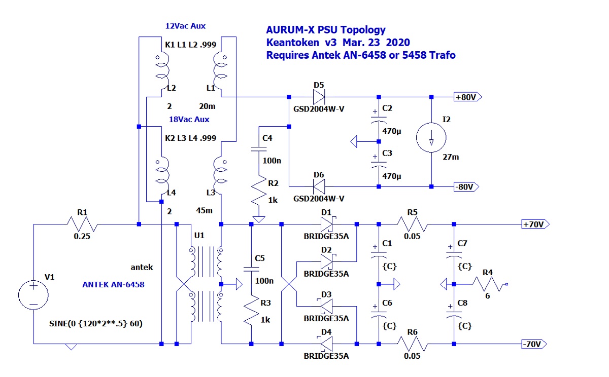
One major design decision was to go with an Antek 500VA or 600VA 58v an AN-5458 or AN-6459, respectively. The 500VA unit actually simulates better if we can believe the spice models that Antek puts out. Not that these transformers that provides auxiliary windings (12v and 18v) which are used to achieve the higher rail voltages for the FE through a half wave bridge. The connection diagram for the various secondary windings must be followed precisely as some phases are flipped. You will have to pay close attention to the PSU topology diagram and use that to correlate to the dot/no-dot leads on the various wires coming from the Antek. This is complicated by the fact that Antek does not label their leads dot/no-dot so some investigative work and experimentation will need to be done with test equipment prior to hooking up at full mains power.
Here is a schematic of the PSU topology to achieve +/-80v for the FE and +/-70v for the output stage:
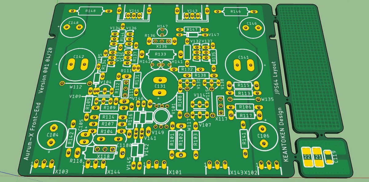
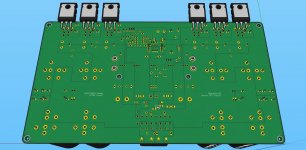
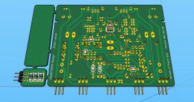
Here is the top view of the FE PCB:
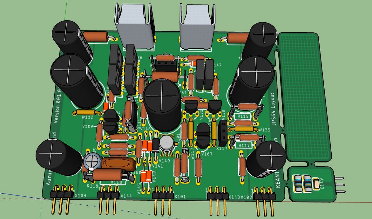
Here is the assembled FE top side:
Here is the assembled FE bottom side:

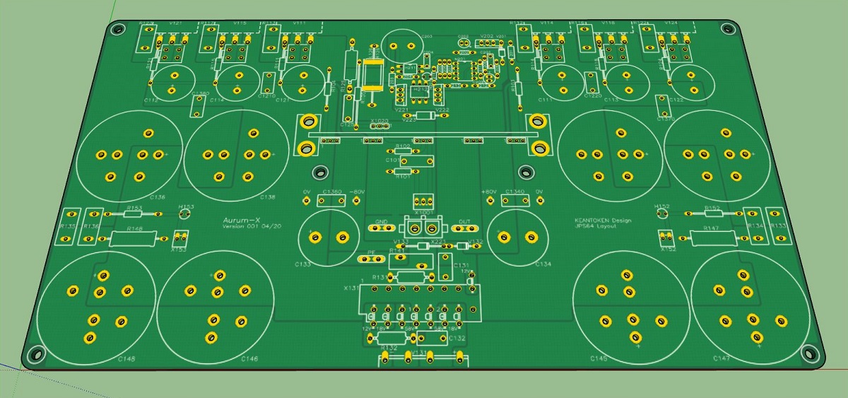
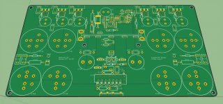
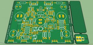
Here is the MB PCB top:
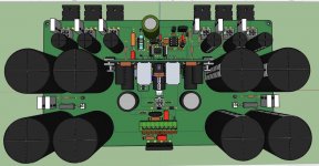
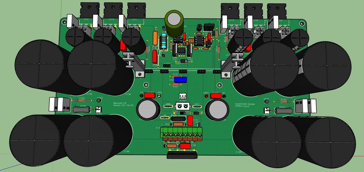
Here is the MB assembled top:
Here is the MB assembled bottom:

A big thank you to Keantoken for a super design and very clever PSU.
And a huge thanks and hats off to JPS64 for another superb layout of the highest caliber!

It's been a while since we have posted an update on this thread, much of it due to everyone's busy schedules and the vastness of this project - requiring a large amount of time to review schematics and double check interfaces, connections, etc. I think we are finally at prototype manufacturing stage though. Here are the schematics for the MainBoard(MB) and the FrontEnd(FE), and various renders of the PCBs and assembled PCBs.
Here is the simplified LTspice Schematic used for the simulation:
The detailed schematics corresponding to the manufactured PCBs are in the PDF's below.
One major design decision was to go with an Antek 500VA or 600VA 58v an AN-5458 or AN-6459, respectively. The 500VA unit actually simulates better if we can believe the spice models that Antek puts out. Not that these transformers that provides auxiliary windings (12v and 18v) which are used to achieve the higher rail voltages for the FE through a half wave bridge. The connection diagram for the various secondary windings must be followed precisely as some phases are flipped. You will have to pay close attention to the PSU topology diagram and use that to correlate to the dot/no-dot leads on the various wires coming from the Antek. This is complicated by the fact that Antek does not label their leads dot/no-dot so some investigative work and experimentation will need to be done with test equipment prior to hooking up at full mains power.
Here is a schematic of the PSU topology to achieve +/-80v for the FE and +/-70v for the output stage:
Here is the top view of the FE PCB:
Here is the assembled FE top side:
Here is the assembled FE bottom side:
Here is the MB PCB top:
Here is the MB assembled top:
Here is the MB assembled bottom:
A big thank you to Keantoken for a super design and very clever PSU.
And a huge thanks and hats off to JPS64 for another superb layout of the highest caliber!
Attachments
-
 Aurum-X-MB-Render-Top-v001.jpg179 KB · Views: 8,767
 -
 Aurum-X-MB-Render-Bot-v001.jpg182.5 KB · Views: 1,349
 -
 Aurum-X-MB-PCB-Render-Top-V001.jpg227.5 KB · Views: 1,356
 -
 Aurum-X-FE-Render-Top-V001.jpg244.2 KB · Views: 8,873
 -
 Aurum-X-FE-PCB-Render-Top-V001.jpg273.3 KB · Views: 1,392
 -
Aurum-X-MB_SCH_001.pdf141.3 KB · Views: 452
-
Aurum-X_THT_FE_SCH_001.pdf120.2 KB · Views: 705
-
 Aurum-X-FE-PSU-Topology-v3.jpg154.9 KB · Views: 8,481
 -
 Aurum-X-FE-Render-Bottom-V001.jpg215.5 KB · Views: 1,376
 -
 Aurum-X-Schematic-v001-LTspice.jpg190.5 KB · Views: 10,653
Last edited:

JPS64 uses Sketchup but I will let him explain his workflow. There are several intermediate post processors I think that take what Eagle generates.
Kicad will generate 3D views directly. (And it will import Eagle files.) (And it's free.)
Disclaimer: I'm a developer.
Disclaimer: I'm a developer.
That´s right but you´ve also to map 3D components and you know that KiCad librairies are a pain in the A... (I suppose you don´t really know the work load for libraries mapping from Eagle after SCH and BRD importing). Layouting is also way to complicated. But all EDA tools have pros and cons, and yes, KiCad is free and support is not bad at all.
I´m using the older 7.5 Eagle version so ECAD/MCAD is to do manually.:
- 3D STEP download
- STEP to STL using FreeCAD
- STL to COLLADA using Blender
- COLLADA to SKP using SketchUp
- eagleUp_export ulp from Eagle to Sketchup
The newest cloud based version (with great 3D mapping tool) works with Fusion and managed libraries, and yes, sadly it´s not free.
JP
Fusion has a very reasonable yearly subscription price if you do this for business and not merely DIY-hobby.
- Home
- Amplifiers
- Solid State
- Keantoken's Aurum-X 300w Amp with LatFETs