
In practice I found that same gate stoppers for both outputs actually work best on a prototype I have using the same exicons.
A good place to start would be lowering R20 in your schematic to 4.7ohms, maybe bump up the capacitor to 220nF, and take care that the capacitor is actually rated for the worst possible dv/dt, as I fried one before...
This is the point where I replace all the compensation capacitors with trimmers and find the optimum. This is 100x faster than trial and error with the soldering iron.
12MHz is pretty high, so it's likely there is too much phase lead, not too little. If there was too little the frequency would probably be lower. 22pF with a 910ohm feedback resistor is actually very little phase lead for an amp so something else probably needs to change. I would try adding a single gate stopper for all 3 MOSFETs on each polarity, make it a 1k trimmer. Find the gate stopper and phase lead values which allow the smallest stable value for the miller cap.
Originally i never hand matched them however after i had these oscillation issues i removed the pairs so there is only one complementary pair currently installed i.e. one N20 and one P20.Are the output fets matched?
I'm assuming you have 3 pairs, just like on your schematic.
If they are unmatched, it will oscillate.....
Thanks - I'll try that tomorrow.In practice I found that same gate stoppers for both outputs actually work best on a prototype I have using the same exicons.
A good place to start would be lowering R20 in your schematic to 4.7ohms, maybe bump up the capacitor to 220nF, and take care that the capacitor is actually rated for the worst possible dv/dt, as I fried one before...
This is the point where I replace all the compensation capacitors with trimmers and find the optimum. This is 100x faster than trial and error with the soldering iron.
The compensation ends up changing when you use more or less pairs. So making it stable with 1 pair does not necessarily mean you can add the rest back and have it stable.
If it were parasitic oscillation, it would probably be 20MHz or higher.
We also don't know about your layout or the source resistors you are using.
If it were parasitic oscillation, it would probably be 20MHz or higher.
We also don't know about your layout or the source resistors you are using.
In simulation, there are several things that can contribute to instability around 12MHz:
Zobel resistor too low. (check)
Gate stoppers too low. (check)
Driver base stoppers too low. (check)
C7 too low.
In the stable simulation I have the zobel network is 3.9ohm+22nF (100nF is fine)
Gate stoppers are 270ohm/180ohm
Driver base stoppers are 100ohm
These values can be seen in the output stage section of the build schematic:
Zobel = I have two zobels of 10 Ohm and 100nF (two off). I'll try 4.7ohms and 220nFIn simulation, there are several things that can contribute to instability around 12MHz:
Zobel resistor too low. (check)
Gate stoppers too low. (check)
Driver base stoppers too low. (check)
C7 too low.
In the stable simulation I have the zobel network is 3.9ohm+22nF (100nF is fine)
Gate stoppers are 270ohm/180ohm
Driver base stoppers are 100ohm
These values can be seen in the output stage section of the build schematic:
View attachment 1085809
Gate stoppers = 220 Ohm (P) and 470 Ohm (N)
Driver base stoppers = 100 Ohm
C7 = 47pF
C11 = 20pF (i'll try increasing this to 47pF)
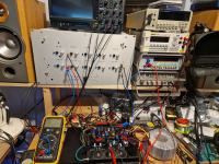
The temp setup i have with earth connections scattered everywhere is probably contributing to oscillations so i'll tidy these up as well and feed back.
Cheers
Dom
Third night of troubleshooting and finally I have figured out the issue - difficult to know if it was only this issue as I’ve went through so many iterations and changes but correcting the temporary earth wiring has solved the oscillation issue. I had mistakenly connected a PWR earth to input earth bypassing the breaking/lifting resistor and creating a loop.
Enough for tonight but now that I know I have it stable I’ll mount it in a proper chassis for full testing.
Enough for tonight but now that I know I have it stable I’ll mount it in a proper chassis for full testing.
Attachments
Yes, grounding the power earth to the input causes positive feedback and would usually cause this sort of issue. Considering everything, this actually looks promising to me. You could say, "the patient is responding to treatment".
I was wondering how all this worked out? I never built the beast as life got in the way.... I was hoping it worked out. 🙂 Looks like 7 months without input. ( I hope someone had good results for their time and investment. I chose to sleep in our bedroom. I still have the boards, and 99% of the other parts, the board can/will be shipped,but I will re-task the parts.
Have it be known, I would have done the project with support, but it didn't happen, "so the decision was written on the subway walls, it tenement halls."
I reached out KT, you are brilliant, but I didn't get the support I would need to do the project. I wish it had been different, I saw some awesome licks in your design, but I would have needed you where an when, like we did with the Wolverine.
You have an amazing mind...
JT
Last edited:
I am unable to do anything because I don't have the parts, plus right now I'm too busy anyways.
You are one of the most brilliant e-engineers I have ever come across, but we all have our demons. I wish you nothing, but the best KT you helped us large on the Wolverine. \
Best
JT
Best
JT
Indeed, it would be nice to have a lateral mosfet counterpart to the Wolverine.
One can hope!
Best,
Anand.
One can hope!
Best,
Anand.
Speaking of Wolverine, did you build a unit for yourself JT?
Even though that amp has more transistors than all my Class A amps combined 🤣, I ended up biting the bullet and got a set of pcb’s🙄.
Even though that amp has more transistors than all my Class A amps combined 🤣, I ended up biting the bullet and got a set of pcb’s🙄.
I was hoping someone else was going to pick up the torch with this project….. looks like I have a very large paperweight.
I am not sure what more is needed in the way of support - all we can do is provide the schematics, BOM, PCBs and answer questions. Until a PCB is populated and trafo wires are connected and MOSFETs bolted to a heatsink, what else can the designer do?
It’s plain old motivation, elbow grease, and thinking hard, and problem solving. This is a new unproven amp and you guys are Alpha testers. Not yet Beta even.
I understand when life or other projects get in the way. But I don’t think it’s fair to blame it on Keantoken for “lack of support”.
I think Shanebou got the farthest and did in fact connect the trafo and installed MOSFETs on a heatsink. What’s the status and what are the questions to make it work?
I’m just a beginner. I am far cry carrying the torch and holding up a team. I’ll happily try things out, make readings and report back. But the level of problem-solving needed for this build is simply beyond my skill set. Without a good deal handholding I just don’t have the knowledge.
No, I never got the final version of the boards. One of the project people sent me an earlier version of it that will work fine, but it's not the latest release. I still have the beta amp here that works, but I don't trust it as we swapped out so much stuff the boards were beat up at the end.Speaking of Wolverine, did you build a unit for yourself JT?
Even though that amp has more transistors than all my Class A amps combined 🤣, I ended up biting the bullet and got a set of pcb’s🙄.
- Home
- Amplifiers
- Solid State
- Keantoken's Aurum-X 300w Amp with LatFETs