Sorry X and KT, I got tied up with a huge Yamaha B2 restore of 3 amplifiers having brought one back from parts status. Also, I take care of my elderly mother and have been busy with that as well. I'll finish up the B2 stuff this week and get back on it. KT said something about a new schematic? I need to go back reread and get up to speed. Does anyone have one working yet?
Without a good team, nothing gets built. 😵 It takes support and info sharing, I don't think that has been achieved here, which is one of the reasons I worked on the B2s. Nothing I have seen in the 2 days since I posted changes my opinion. I guess, I'll write off the cash as lesson learned.
Last edited:
Hi TT,
I am not sure what more you were expecting as a verification builder. I have done this before many times and what is provided are the design, schematics, BOM, PCBs, and we are here to answer questions. It’s up to the builder to execute and if you run into problems, we help debug and solve the problem. Let me know what it is you think you specifically need that has been missing? Are you missing any info, data, details on how to assemble?
You have a state of the art design by a top notch design team of Keantoken and JPS64 here. The third leg of the stool is the builder.
The things that makes this project more difficult are the complexity of the design and the cost of parts. They are substantial and that’s no joke, and I know that can be an issue for some.
For me, it was all about availability of my free time to pursue a “hobby-build”.
Last edited:

You could always send me the parts and let me build it, although most want to build their own amp in the spirit of DIY. It's hard to watch this thread when DIYAudio randomly skips notifications, and posts start suddenly after long periods of absence without warning when you have started another project. I can't be on call constantly for this thread (or anything else), but I don't deliberately ignore it.
I ended up helping someone fix a Yamaha M2 recently. The speaker relay contacts were resistive and the sound would fade in and out. It works fine after cleaning the contacts with alcohol.
I ended up helping someone fix a Yamaha M2 recently. The speaker relay contacts were resistive and the sound would fade in and out. It works fine after cleaning the contacts with alcohol.
The first thing is an updated schematic that KT mentioned a few posts ago. I have most of the parts, at least the ones that have not been changed in the process, I'm sure there are some. I added you to the meeting software, I think you responded one time and I asked another question and never got an answer KT. I finally just deleted the forum. If you can't be present, for the guys that spent a grand, not because they want, or need another amp, but because they wanted to help get a new design going. I have 20+ great working amps here now. I certainly don't need another if the support isn't there. If that takes you bringing up this forum twice a day, to get around any notices, then that's what you should do. What's it take 5 secs?
As to shipping you a thousand bucks or more parts to have you build it...? I'll pass on that one. You know the kind of support I mean KT, as you helped us complete the Wolverine Amp. That's what I'm talking about, this amp is untested and you need a good support group, or perhaps, a better engineer to build it. 😉
I have to get off to work, I shall consider what has been said.
JT
The other place wasn't working because I lost my means of accessing it. It did not occur to me to talk to you since it had been so long since anything had happened. If you had contacted me here, I would have responded. It definitely wasn't my intention but I was having to jump through a lot of hoops to stay connected there, and it just wasn't sustainable.
Based on what the other builder said before progress stalled, the amp may have been working fine and just needed some trimmers set. Nothing went terribly wrong, so I think that is a good sign.
Based on what the other builder said before progress stalled, the amp may have been working fine and just needed some trimmers set. Nothing went terribly wrong, so I think that is a good sign.
Here are all the latest schematics, BOM, stuffing diagrams, etc. including the rev2 of the FE board. Let me know if you need anything else.
Attachments
Last edited:
I have a mono block built and ready to be tested but I lack the knowledge to proceed. I need a in detail step by step start up procedure. Or a phone callSorry X and KT, I got tied up with a huge Yamaha B2 restore of 3 amplifiers having brought one back from parts status. Also, I take care of my elderly mother and have been busy with that as well. I'll finish up the B2 stuff this week and get back on it. KT said something about a new schematic? I need to go back reread and get up to speed. Does anyone have one working yet?
Is it your first project?I have a mono block built and ready to be tested but I lack the knowledge to proceed. I need a in detail step by step start up procedure. Or a phone call
First time shooting is a procedure that has many times explained in the forum.
In case you have missed this here are the basic.
Adjust Bias trimer for zero bias.
Do not connect any load in amplifier output.
Connect a short link between INPUT+& INPUT GND.
Connect an incandescent lamp in series with the
primary coil of power supply transformer.
Have a break🙂
Connect a D.C voltmeter between OUT+ & GND(POWER SUPPLY 0 V).
Power the amplifier.
If everything is ok,you will see 0v or something up to 1V D.C in the voltmeeter,and the lamp NOT glowing.
Leave this under voltage for a little.
Power amplifier off.
Take a deep breath!
Power the amplifier on again,leave this for a while and start to adjust the bias trimer when you monitor the D.C voltage across the emiter resistor.
Not possible to adjust the correct current becouse of the power supply low voltage(lamp in series).Adjust for something a little different than 0mV.
May be see the lamp glow a little.,this is ok.
Leave this way for a little.
Power off.
Connect the D.C voltmeter between amplifier out and GND(Power supply 0 v).
Power on,read the out D.C Voltage.Up to 1V D.C is ok.You will adjust this for 0 V D.C latter.
If everything is ok you have pass the firt soothing test!
Disconnect the incandescent lamp and restore the circuit(You will connect primary coil of Power Supply transformer directly at your mains this time.
Be sure that inp.short link is still in place.
Connect a D.C mV meter across one of the emiter resistor(0.22 Ohm).
Power the amplifier on.
Look at the voltmeter,everything like 5...10....20 mV is ok for now.
If so,leave for about 10 minute
Then if you know the exactly recommended current adjust for this.
Power off.
Connect a D.C voltmeter between OUT+ & GND.
Power on again.
Adjust offset trimer for 0 V or so reading.
Power off.
Connect a D.C voltmeter across the emiter resistor (0.22 Ohm). again.
Power on.
Leave for about 20 minutes.
Readjust the bias trimer.
That's it!
Power off.
Connect a CHEAP speaker in amplifier Out.
Remove the input short link.
Connect Music source in amplifier input.
Keep volume low.
Power on........do you hear something..........?
If you can hear a low but undistorted music,everything is ok for now!
Last edited:
Looking at the schematic i see another adjustment for the VAS current.
Adjust this before the final bias current adjustment.
Adjust this before the final bias current adjustment.
The adjustments are as follows, if the PCB or schematic says differently ignore it. I am very sorry for all the setbacks.
X136: output stage bias
X117: Output DC offset trim
X111: VAS bias current
1: Before startup, turn the X136 to it's lowest value as measured across R136. Turn X11 to it's lowest value as measured across R111
2: After startup, adjust X111 so that the voltage between the collectors of V132 and V137 is equal.
3: Raise X136 to set the output stage bias so there is 22mV across each 0.22ohm resistor.
4: Check #2 is correct and repeat 2 and 3 as necessary.
Correction, many pages ago the bias was upped to 33mV per source resistor to reduce higher order harmonics (according to simulation).
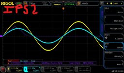
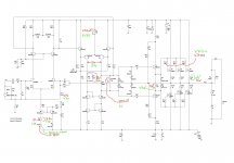
I've been following this thread since the start as I was designing and testing various lateral FET topologies at the time. As the output section of my amplifiers are very similar to the Aurum I thought it wouldn’t take much effort to change the front end and give this Aurum a listen. After connecting everything up as per the attachedd I powered both the front end and output stage with 60V rails (just for convenience). After correcting a slight DC offset I couldn’t balance the voltage between the collectors of V132 and V137 without reducing the VAS bias (R112) considerably (down to 600 Ohm). Once the voltage between the collectors was zero any increased output stage bias would cause the amplifier to go into 8 - 12 MHz oscillations with around 500mV to 1V on the output. So I’m currently sanity checking my test rig and I’ll report back when hopefully I find a silly error. During this check I did notice that your bootstrap capacitor C142 has the positive polarity connected to the negative VAS rail.
Attachments
Gate capacitance for N and P Exicon fets are not identical, so one of the reasons for oscillation could be the fact that gate stoppers for N and P fets are identical.
Usually N device has lower capacitance than P device, so some designers ADD extra cap on N device to make them equal.
Example: Rod Elliot's P101.
If capacitances are not equal - that may cause oscillations.
Another way of dealing with this issue, is by using DIFFERENT gate stoppers, using formula RC = constant, where R is gate stopper resistor, and C is input capacitance of the FET. Adjust R on the both devices, so RC value are equal on upper and lower FETs.
Example:
Let's say the 2SJ162 has a gate stopper of 100 Ohm and a gate
capacitance of 900pF, the RC time constant is just RgatexCgate=RC time constant,
so 100x900x10^-12=90nS. If we want 'balance' we need a resistance on the gate of
the 2SK1058 that gives the same time constant.
So, Rgate x 600pF = 90nS, solve for Rgate. In this case Rgate needs to be 150 Ohm.
For Exicon double die devices I was using upper Rg=470 Ohm, and lower Rg = 220 Ohm in similar OSes.
Not saying that this will fix everything, but it might be the culprit... Especially if multiple pairs are used...
Brief update -
Thanks Minek, i revised the gate resistors to match RC constants (I’ve never had issues with this in the past but thanks for pointing this out) it has improved stability but it still oscillates when the OPS bias is ramped up (just not as severe as it was previously).
I'll have a play around with C11 and miller compensation caps on the drivers - I have spaces for them on the PCB for this very purpose. D.Self does use higher values in his examples.
Thanks XRK for your suggestion - I tried 47pF but no difference to the oscillation.
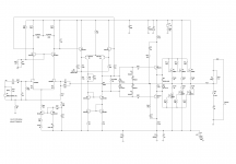
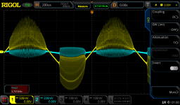
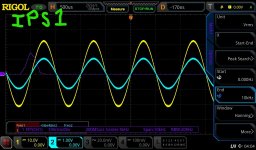
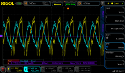
I have two input stage boards to make trouble shooting easier. Both amplify the input signal well but I just cannot up the OPS bias or it instantly oscillates. See attached two screenshots from oscilloscope of each IPS amplifying and another screenshot of the oscillation with 500ns wavelength.
I also done a comparison of voltages between the two IPS boards - there is another issue with IPS2 as only 252mV across R5 which should be 1.5V to 2V.
I’ve had enough for tonight but I’ll pick it up again tomorrow evening.
Cheers
Dom
Thanks Minek, i revised the gate resistors to match RC constants (I’ve never had issues with this in the past but thanks for pointing this out) it has improved stability but it still oscillates when the OPS bias is ramped up (just not as severe as it was previously).
I'll have a play around with C11 and miller compensation caps on the drivers - I have spaces for them on the PCB for this very purpose. D.Self does use higher values in his examples.
Thanks XRK for your suggestion - I tried 47pF but no difference to the oscillation.
I have two input stage boards to make trouble shooting easier. Both amplify the input signal well but I just cannot up the OPS bias or it instantly oscillates. See attached two screenshots from oscilloscope of each IPS amplifying and another screenshot of the oscillation with 500ns wavelength.
I also done a comparison of voltages between the two IPS boards - there is another issue with IPS2 as only 252mV across R5 which should be 1.5V to 2V.
I’ve had enough for tonight but I’ll pick it up again tomorrow evening.
Cheers
Dom
Attachments
- Home
- Amplifiers
- Solid State
- Keantoken's Aurum-X 300w Amp with LatFETs