Here you see a clamping method :http://web.telecom.cz/macura/doc_open_phono_en.pdf
It limits the input to around plus-minus 0.65V so for a higher clamping voltage you need zeners.
It limits the input to around plus-minus 0.65V so for a higher clamping voltage you need zeners.
Thank you Joachim.
Will try the zeners in parallel with the input for now.
Anyway this was a positive experience for me. Learned how to repair the amp and also tought me never to unplug cables while the power amp is on. (The riaa amp I was using is capable of swinging 20v at the output....)
Will try the zeners in parallel with the input for now.
Anyway this was a positive experience for me. Learned how to repair the amp and also tought me never to unplug cables while the power amp is on. (The riaa amp I was using is capable of swinging 20v at the output....)
Here you see a clamping method :http://web.telecom.cz/macura/doc_open_phono_en.pdf
It limits the input to around plus-minus 0.65V so for a higher clamping voltage you need zeners.
Did not find a clamping method in pavel macura's riaa......
At the input are two diodes. One is from the input to the positive supply and one is from the input to the negative supply.
Here the output is clamped to 40V to avoid electrical shock :Röhrenverstärker Bausatz
You can use the same circuit at the input but clamped to lets say 4V.
You could use an anti parallel string of conventional diodes, say 3 x 1N4148 in series plus 3 x 1N4148 in series but turned around. That will give you a 6 x 0.65 V = 3.9V clamp.
You can use the same circuit at the input but clamped to lets say 4V.
You could use an anti parallel string of conventional diodes, say 3 x 1N4148 in series plus 3 x 1N4148 in series but turned around. That will give you a 6 x 0.65 V = 3.9V clamp.
Maybe you could use Leds but i do not know if they are fast enough.
So far i only used the output clamping method with tubes.
Never tried it at the input.
There is of cause the posibility to put a current limiter in the output stage but somewhow i do not like that because it will limit the peak current output.
So far i only used the output clamping method with tubes.
Never tried it at the input.
There is of cause the posibility to put a current limiter in the output stage but somewhow i do not like that because it will limit the peak current output.
Thank you so much.
Learning is a rump up process... de more you know the more you discover you must know in an exponential manner
Learning is a rump up process... de more you know the more you discover you must know in an exponential manner
Here is a more sofisticated clipper that compresses before it cuts off :http://www.diyaudio.com/forums/analog-line-level/222139-soft-clipper-central-station.html
Opened a new thread dedicated to the "Assemblage Power Amp" http://www.diyaudio.com/forums/solid-state/258549-assemblage-power-amp.html#post3978099
I would really appreciate your input.
I would really appreciate your input.
Here is a more sofisticated clipper that compresses before it cuts off :http://www.diyaudio.com/forums/analog-line-level/222139-soft-clipper-central-station.html
That's a subject that did have my attention a while back 🙂
Attachments
Incredibly complex it seems.... Can you give me some guidance ?
How could I implement that on the Nobrainer ?
How could I implement that on the Nobrainer ?
Incredibly complex it seems.... Can you give me some guidance ?
How could I implement that on the Nobrainer ?
I would not 🙂 the first one is a try to outdo D. Self (and it does) and the second one is the D. Self design (from his book (but fixed)) (it adds some HF artifacts that I do not like). Currently I'm thinking of a better, easier and less complex (but still secure and 'High-end' system) 🙂
Regards,
Frans (Mastermind 🙂)
I will then wait for your version 🙂
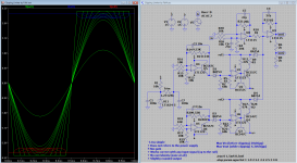
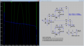
The miller-cap should be (in my last schema) 10p (NOT 100 🙂) (so you where using 100?) The picture shows the 'phase-shift' using the faulty 100p capacitor! Almost 2uS
See also #351 http://www.diyaudio.com/forums/anal...rainer-nobrainer-discrete-36.html#post3835270 🙂
P.s. Your scope shows about 2uS of shift.
HI
I would like made a 100W 4ohm power buffer with an opamp based VAS
Your input buffer (just CCS) is better than input Diamond buffer ?
Thanks
We talked about other ways to put Opamps at the input of a power amplifier.
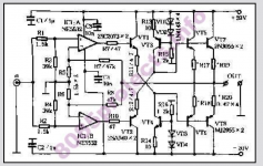
I find this design quite interesting.
It is a kind of instrumentation bridge.
It gives a 20W class A amplifier.
Sorry for the hard to read schematic.
The original is that poor and i had to blow it up.
I find this design quite interesting.
It is a kind of instrumentation bridge.
It gives a 20W class A amplifier.
Sorry for the hard to read schematic.
The original is that poor and i had to blow it up.
Attachments
HI
I would like made a 100W 4ohm power buffer with an opamp based VAS
Your input buffer (just CCS) is better than input Diamond buffer ?
Thanks
Sébastien, I do not know why you asked this in a PM and then post the same question here...? but here is a copy of the answer that I gave to the PM.
PM said:Hi Sébastien,
That is not what I am going to say, if any thing that I made is better (or worst) then others, it needs to be judged by those others, my answer is: Ask RCruze
On the brighter side, I think that using the referenced configuration, with an OPA50x high voltage op-amp, will yield a very good amplifier.
Regards,
Frans.
Here is another opamp driven poweramp.
It has an interesting bootstrap idea :http://www.by-rutgers.nl/SSA-30W.html
It has an interesting bootstrap idea :http://www.by-rutgers.nl/SSA-30W.html
- Status
- Not open for further replies.
- Home
- Source & Line
- Analogue Source
- JG´s Nobrainer and Nobrainer Discrete