
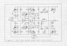
It sims ok IMO
And here is an image:
I did do a quick simulation and it looks o.k., maybe it is best if build first and then (depending on experience) steer it in one or another direction. Until the 'High-end' in Munchen I do not have much time anyway 🙁 and 🙂
I did do a quick simulation and it looks o.k., maybe it is best if build first and then (depending on experience) steer it in one or another direction. Until the 'High-end' in Munchen I do not have much time anyway 🙁 and 🙂
Thank you for your input Frans. I really do appreciate it.
You made me quite comfortable and I will now start collecting parts.
I like the idea of being able to null input offset by trimming the vbe biasing of the input bjt... even if it depends on the previous preamp output impedance...
I am pushing my way in in the TGM8 thread.... There is also a possibility to develop it with a jfet input stage (maybe with a folded cascode)....
Let us talk a bit about crossover distortion....
For small signal (low bias currents), Zout(small)=(re' + Re)/2 because both halves are working in parallel.
For large signal (high currents), Zout(large) =Re because re' is so small it can be neglected.
Crossover distortion is minimized by making small signal and large signal output stage gains equal.
In theory, using Re = 0.22ohm ideal idle current would be 118mA so re'=26/118=0.22 and Zsmall=(re'+Re)/2=(0.22+.22)/2=0.22
Zlarge=Re=0.22 and so Zlarge=Zsmall
But I found that the amp excels at 180mA bias
So we have two options:
First - In reality re' is not 26/180 but 26/180 x Factor(1.5)= 0.22 = Re and I hit the sweet spot.... or...
Second - Ic=180mA so re'=26/180=0.144 and maybe I should reduce Re from 0.22 to 0.14 so I would reduce crossover distortion.
Waiting for your comments.......
Indeed I use the DCB1 powered with two very special shunts. It conveys a really wide soundstage with really stunning insight regarding microdetail.
Much better than my previous pedja buffer that in itself was already superior to my initial LM4562 preamp.
http://www.diyaudio.com/forums/analog-line-level/255884-super-chip-preamp-v1-2-lt1363.html
I try to explain :
Degeneration is good for linearity. In that sense a 0.47 Ohm resistor in the emitter feed is good, better then say 0.235 Ohm. BUT that stage will not work as a perfect buffer any more because VOLTAGE GAIN is not times one ( 1 x 1 = 1 ) any more.
When you use TWO output transistors, both with 0.47 Ohm degeneration in parallel you have both advantages : good CURRENT linearity and good VOLTAGE linearity.
The net resistor is 0.47 Ohm divided by two = 0.275 Ohm BUT with double the current from a single pair degenerated by 0.275 Ohm. All clear ?
Thank you for the clarification, but that did not exactly answer my question.
to have the same gain at small signal and large signal we should have Re = re'
In this case we are even more far apart. The two transistors in parallel will have half total re' at small signals and we grew Re from 0.22 to .275
to have the same gain at small signal and large signal we should have Re = re'
In this case we are even more far apart. The two transistors in parallel will have half total re' at small signals and we grew Re from 0.22 to .275
That 0.47 Ohm was only an example.
In the Nobrainer you build you found that 180mA idle works best with 0.22 Ohm.
This is a bit higher then the calculated value.
As Frans hinted it may be that the output transistors will have more beta ( hfe ) at that idle ( 180mA ) then the calculated 118mA so the circuit is more linear with higher idle.
Still i think that a second pair of output transistors ( also with 180mA and 0.22 Ohm ) will be even better.
Use BD139/140 and a bit more current in them (I think) that will give them a bit more 'authority'. Also add a few base stopper 5 to 10 ohm will do, that distributes Ib among the output transistors and enables local compensation (when needed). Move the .22 ohm resistors to the emitters and increment to .5 ohm (like Joachim I like the higher Re values). And last, why not finish the opamp replacement experiment first?
- Status
- Not open for further replies.
- Home
- Source & Line
- Analogue Source
- JG´s Nobrainer and Nobrainer Discrete