I have already bought UJ3N065080K3S, I will receive the package at the end of this month.
We have already checked T3, T4, T5, T6 - 2SJ103GR, 2SJ103BL, T7-T10 - J112 (45 mA). Things are good.
The amplitude across the UJ3N065080K3S gates is 13 V.
It depends on the steepness of T3, T4.
The buffer acts as a repeater. He has a low Rout.
We have already checked T3, T4, T5, T6 - 2SJ103GR, 2SJ103BL, T7-T10 - J112 (45 mA). Things are good.
The amplitude across the UJ3N065080K3S gates is 13 V.
It depends on the steepness of T3, T4.
The buffer acts as a repeater. He has a low Rout.
I would assume 2sj103 can be substituted with 2SK170?
2sj103 - P-channel, 2SK170 - N-channel.
Thank you for the updated info jpatay. Sorry about the mix up on the N vs P channel. For some reason I had a brain fart on that. Thanks for correcting me.
This is a very exciting concept using the newer and more available SiC jfets. I'll be gathering parts soon.
A question on the revision to the buffer. Does this make the V2 PCB's obsolete or can they still be used with or without modifications?
This is a very exciting concept using the newer and more available SiC jfets. I'll be gathering parts soon.
A question on the revision to the buffer. Does this make the V2 PCB's obsolete or can they still be used with or without modifications?
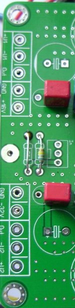
The board fits, you need to put jumpers instead of the upper transistors (D-S). Yurik_V will give a link where to order PCB.
Last edited:
The pcb is universal, suitable for all amplifier options. You can order the pcb yourself here: JFET-only Circlotrons without negative feedback v2 - Share Project - PCBWay
Link for ordering power supply boards: Power supply unit for JFET-only Circlotron - Share Project - PCBWay
Link for ordering acoustic protection boards: Simple Speaker Protection - Share Project - PCBWay
Link for ordering power supply boards: Power supply unit for JFET-only Circlotron - Share Project - PCBWay
Link for ordering acoustic protection boards: Simple Speaker Protection - Share Project - PCBWay

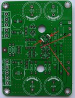
Not. It is necessary to put jumpers instead of T7 and T10. But then you need to cut the tracks on the SiC gates and set the jumpers as shown.
But it's better to leave it as it is. With T7-T12, this circuit also works well.
P.S. The circuit in the figure is completely different, as an example.
But it's better to leave it as it is. With T7-T12, this circuit also works well.
P.S. The circuit in the figure is completely different, as an example.
Attachments

Last edited:
Thank you jpatay. I think I will stay with the original layout rather than cutting up the board. Another question, does this amp require balanced input or does one input pin jumper to ground for SE operation?
Everything is correct, it is better to leave everything as it is. I didn't like the balanced input. It will be necessary to put a jumper on one resistor.

I also noticed from older photos it doesn’t look like you have any of the large caps 10,000uf installed in the board. Are they not needed? Would they hurt the sound or help?
If the power supply is located close to the board, then only MKP capacitors can be installed on the board.
See for yourself what is best for you.
See for yourself what is best for you.
I also noticed from older photos it doesn’t look like you have any of the large caps 10,000uf installed in the board. Are they not needed? Would they hurt the sound or help?
They won't hurt. I saved a little 10,000 uF.😉
Some measurements
Why is the 2nd harmonic dominant? I would have expected to see the odd 3rd and 5th harmonics, but not even harmonics.
Why is the 2nd harmonic dominant? I would have expected to see the odd 3rd and 5th harmonics, but not even harmonics.
The theory is that field-effect transistors ideally have a quadratic throughput.
Therefore, for them odd harmonics are not typical.
Especially. when it is helped by circuitry. As here. I will say more.
One in the output stage bipolar transistor in a similar circuit is also not prone to odd harmonics. Although not every transistor is suitable for this.
Hi
How does it work?
Thanks in advance
The answer is in message # 7.
Sure. However, the even harmonics should cancel out due the symmetry of the circuit. Why is this not the case here?The theory is that field-effect transistors ideally have a quadratic throughput.
Therefore, for them odd harmonics are not typical.
Especially. when it is helped by circuitry. As here. I will say more.
One in the output stage bipolar transistor in a similar circuit is also not prone to odd harmonics. Although not every transistor is suitable for this.
- Home
- Amplifiers
- Solid State
- JFET-only Circlotrons without negative feedback