Yes you could do that, but it looks like a tool that is not very sited for the task. That would take developments and personal time to just test it and identifying if it is usable for your case or not. With fairly good laser distance sensors floating at about $120-150 on ebay, I would not use this one.View attachment 1434599
The response curve of the SHARP IR (GP2Y0A51SK0F) sensor shows a very steep slope within the first centimeter, indicating high sensitivity in this range. However, positioning it this close to the driver is not feasible. Between 2 and 5 cm, the slope becomes more gradual, with the voltage dropping by approximately 0.4 volts for every 1 cm. This means that for each millimeter, the voltage changes by 0.04 volts. Is it a sufficient resolution for accurate measurements?

Introduce one if possible. Thank you.Yes you could do that, but it looks like a tool that is not very sited for the task. That would take developments and personal time to just test it and identifying if it is usable for your case or not. With fairly good laser distance sensors floating at about $120-150 on ebay, I would not use this one.
Thank you. Its response time is less than 1ms which is suitable for alternating movement of the diaphragm, but what is the "Readiness delay" in its specs?I got Banner Engineering lg10a65puq for like $100. Needs speed calibration on your side if you are going to work the driver at Fs, but otherwise I believe it is more linear and more suited. Also gives better output. Working range about +-50mm.
Yes it obviously has it's limitations.
Just since it was not mentioned in this thread directly.
Obviously not suited for high power, high xmax subwoofers trying to test limitations.
Will do the job for lower power drivers midranges, midwoofers etc.
But that was not what the OP directly asked for either to begin with.
Physically reading cone offset also has it's challenges even using laser as was discussed here.
You need high accuracy, very low scan times, a system that supports a high transfer rate etc.
And all that also points to a system that is inherently sensitive to interferences.
ofc some things can be handled in buffers/storage temporary etc.
The full rig certainly will get into my wallet. The probe itself is the cheapest part. €500 oscilloscope is on its way. That one will capture and help analyze things fast and precisely. Then some nonresonant probe and speaker mounting rig with simultaneous physical distance measurement tool too, would not raise my eyebrow if it was €500 too. Then weights, tensometer, and dozens if not hundreds hours of work. NOT cheap. Didn't pretend it is.system that supports a high transfer rate etc.
And all that also points to a system that is inherently sensitive to interferences.
ofc some things can be handled in buffers/storage temporary etc.
Interesting and useful device. REW can measure all these parameters except for those related to symmetry. and overall, this device might be a complete version of REW method.
Last edited:
Very Interesting - I hope you are planning to see this through. Looking forward to your posts on the progress. And if we could brainstorm suspension non-linearity will be great. (You can make this into a project for group buy w.r.t. the costs you are facing now)The full rig certainly will get into my wallet. The probe itself is the cheapest part. €500 oscilloscope is on its way. That one will capture and help analyze things fast and precisely. Then some nonresonant probe and speaker mounting rig with simultaneous physical distance measurement tool too, would not raise my eyebrow if it was €500 too. Then weights, tensometer, and dozens if not hundreds hours of work. NOT cheap. Didn't pretend it is.
DATS LA obviously works similar to what I already described in post #20 and #29. There are two differences:
Heinrich
- DATS generates the excursion with DC I use pressure/vacuum
- DATS seems to calculate the excursion from the Thiele Small Parameters I measure it with a triangulation laser (see also https://www.artalabs.hr/AppNotes/AN7-Estimation_of_Linear_Displacement_with_STEPS.pdf)
Heinrich
Based on force and acceleration formula?DATS LA obviously works similar to what I already described in post #20 and #29. There are two differences:
Regards
- DATS generates the excursion with DC I use pressure/vacuum
- DATS seems to calculate the excursion from the Thiele Small Parameters I measure it with a triangulation laser (see also https://www.artalabs.hr/AppNotes/AN7-Estimation_of_Linear_Displacement_with_STEPS.pdf)
I can't answer your question in detail. Neither the manual nor the patent description mentions this.
But using the level of the low-frequency voltage and the corresponding measured Thiele Small parameters (BL, Cms), the excursion can be calculated.
Regards
Heinrich
But using the level of the low-frequency voltage and the corresponding measured Thiele Small parameters (BL, Cms), the excursion can be calculated.
Regards
Heinrich
I very much doubt that - not to negate you bluntly though. If there is such math, it would be most helpful to get hands and eyes on it.
I think one way to go about it would be to read Klippel documentation and application notes. Reduce the application scope, use simpler sensors and hardware for diy. High accuracy, industrial application etc. can be sacrificed. II
Requires a lot of out of the box thinking and maybe some people here can help with brainstorming some of the challenges here. I agree with Crashpc - it is the maths - that is the challenge , to be able to construct the equation that needs solving for. II
Being able to gauge - Suspension linearity to motor linearity and the suspension systems ability to inhibit the coil from moving out of the gap, will help understand driver performance - Under Large Signals.
And this will help the DIY community with choosing drivers. As Large Signal Performance is not always published.
Is there a difference between the Lorentz force for AC and DC current?I very much doubt that - not to negate you bluntly though. If there is such math, it would be most helpful to get hands and eyes on it.
My question has a purpose.
DATS LA and the Klippel LSI Analyzer work differently.
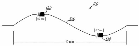
DATS LA measures neither displacement nor sound level. Ultimately, everything is derived from the TSP. A very low-frequency signal (e.g. 0.1 Hz) with varying levels is used to generate the operating point. A 0.7-second sweep for the impedance measurement is superimposed on this signal, the level of which is so low that it has little or no influence on the operating point (see attached pic)
The TSP for the respective operating point is calculated from the sweep. Once I have the TSP for the operating point, I can calculate the frequency response and, of course, the displacement (or simulate it, e.g., with VCAD). Whether 0.1 Hz is more AC or DC is debatable. In any case, it does not correspond to the dynamic excitation of the Klippel Analyzer.
Attachments
Last edited:
DATS LA will be limited to analyze this important characteristics of the suspension system. (to get favorable results in suspension linearity - a driver can utilize a larger than required spider and larger roll of surround that will allow unrestricted movement beyond x-max in both directions)suspension systems ability to inhibit the coil from moving out of the gap
Feel free to light fire under my butt mate, that's actually what's needed. I am somewhat cognitively tired and my math is rather weak nowadays. I count with my fingers. 🤭Is there a difference between the Lorentz force for AC and DC current?
My question has a purpose.
Yes I think there is substantial difference. Though in context of usability, I don't claim if one is better than the other. I am not sure if static model is actually more usable, but for the time being, I am fan of that one. It would take to compare static and dynamic measurements and correlate them to THD on few cases.
- Home
- Loudspeakers
- Subwoofers
- Is there a DIY technique to measure the BL curve of a woofer?