Believe that Dyne analytics co-founder is in this forum, maybe he can help with some inputsIs there a difference between the Lorentz force for AC and DC current?
Attaching some Klippel & Krichner docs too.
Attachments
-
Dyne Analytics - Load Lines 15Apr2011 wmv6.pdf464.9 KB · Views: 52
-
Diagnosis_and_remedy_of_Nonlinearities_00.pdf540.4 KB · Views: 47
-
Assessing_the_large_Signal_performance_of_Loudspeakers_02.pdf402.6 KB · Views: 40
-
Driver Measurement by current - 2.pdf318.4 KB · Views: 49
-
Driver Measurement by current.pdf804.9 KB · Views: 46
-
LoadspeakerMeasurementTechnology.pdf1.4 MB · Views: 55

Been busy, I have yet to look into the materials. But I will.
The basic rig for rudimetary testing is materializing! First THD measurements tests done. Crashpc happy! 🤭

The basic rig for rudimetary testing is materializing! First THD measurements tests done. Crashpc happy! 🤭
Guys, this is one of the eye opening and maturing session.
I tried to go the Klippel way, with help of AI constructing some python scripts that could help me solve the math of motion, and after feeding it my scope data, got sick of the assumptions, approximations and mathematical translations, possibly giving inaccurate results I see in various measurements all over the internet.
So I was like "now I'm dead set on the DC approach, this will be very exact measurement", till I looked at some measurements again, and remembered/reviewed the fact that speakers have DC offset in motion. It doesn't matter much how linear the susension and magnetic circuit is at DC, because it will not be true when producing sound. What is the point of obtaining misleading data that does not translate into real world behavior?
I still have that fighting mood inside me, but at the moment it looks to me like the only thing that matters truly is the mechanical THD and sustainable output (THD + displacement at power capacity). On top of that, I played with various drivers, and found out that even at ~1.5-2.0% of THD in bass, some drivers are able to sound really terrible, plagued by mechanical noises that are unbearable in my book, and so the question rises, what's the point.
What's the point of "single measurememt" of a driver working luckily enough to throw the cone far enough with suspension braking it in round enough movement trajectory that sounds good now at Fs or any single tone, when in the restricted space of a nonlinear behaving enclosure, the outcome will not be anything like it.
Time to stop for a moment and really "meditate" on what piece of data I want from this. The free-air to in-box change is big enough to shatter anything we could assume about the speaker.
This... Is... Not Sparta certainly, but really difficult moment in realisation.
It is just a "scope unpacked sensor taped to tripod" very first setup to test the gear function. In time, some metal rig for sturdy speaker mounting with membrane standing normally horizontally will be built, as well as more precise positioning rig for the laser probe, and verification with calipers could be possible and fast. The linearized output of the probe goes to the scope, when needed it is further filtered by mild LPF, then FFT is applied, harmonics levels are read and THD is calculated.
With Klippel approach, current and voltage needs to be read out, and with the cone motion measurement, it can be run through motion equations that ChatGPT provided.
Though I am not happy with some assumptions for these equations. I am not happy with the DC approach either.
Today, even the THD approach bugs me. Because every physical system (speaker build) has its excursion maxima in frequency very different. Low tuned ported box might peak at 30Hz, high tuned box mught peak at 50-60Hz. Usual THD measurements go with a voltage sweep that inevitably results in highest THD in the lowest frequencies, so we might not know how the speaker behaves at Xmax at 50Hz, unless it is particular test of a system, and not just a speaker alone (talking about Xmax specification of some manufacturers based on THD).
The problem of specification of the test method itself really exploded in my face, and I have hard time understanding what data is even relevant for me.
It looks like I do not like any of the conventional approaches.
I wish you had a driver whose entire large signal parameters is known from - best would be Klippel. Independent of the technique you develop - if you have a driver with its measured values - you can then benchmark your way.
If it is THD alone - as posted on this thread - Arta has this feature with a laser sensor, however if THD is knows - the question arises from where ? I think this is what you are trying to determine.
If it is THD alone - as posted on this thread - Arta has this feature with a laser sensor, however if THD is knows - the question arises from where ? I think this is what you are trying to determine.
The issue that the Klippel data is not to be trusted on my side at the moment. What I see is some leakage between Kms(x) and Bl(x) in these measurements that I don't like/agree with. So such comparison is close to irrelevant to me.
Yes, The THD specs is usually too arbitrary. What is needed is something along the lines of excursion plot in frequency at 10% THD limit (where sensible) between 10Hz and 60Hz. Though running possible Xmax at 60Hz will be ugly and dangerous to quite a few speakers.
Yes, The THD specs is usually too arbitrary. What is needed is something along the lines of excursion plot in frequency at 10% THD limit (where sensible) between 10Hz and 60Hz. Though running possible Xmax at 60Hz will be ugly and dangerous to quite a few speakers.
Leakage?What I see is some leakage between Kms(x) and Bl(x) in these measurements that I don't like/agree with. So such comparison is close to irrelevant to me.
You're aware that a full Klippel dataset is A LOT more involved and contains a lot more data?
For an easier BL approach:
https://www.ant-novak.com/pages/speaker_params/
Last edited:
Some time ago, I was able to perform the above-mentioned comparison between Klippel and alternative methods (in this case similar to DUMAS). The DUT was a Visaton AL130. I would like to emphasize that the same unit was used in both measurements.
Regards
Heinrich
Regards
Heinrich
Attachments
I see different volumes?Some time ago, I was able to perform the above-mentioned comparison between Klippel and alternative methods (in this case similar to DUMAS). The DUT was a Visaton AL130. I would like to emphasize that the same unit was used in both measurements.
Regards
Heinrich
They were all tested in the same volume incl Klippel?
Okay, because that can sometimes shift the results a little bit.No, the Klippel measurement was free air and the "DUMAS" measurement was (to verify the influence of the test volume) in 13 liters and in 59 liters.
But as you mentioned, in this particular case it doesn't seem to be effected that much. 👍 🙂
Interesting results, according to their specs, cone excursion should sit around 6mm (these days they even say 8.5mm, but that's just nasty).
According to these measurements, it's more like 5-5.5mm @ 82% BL
You have access to both systems - wow ! . I think it will help Crash PC if he is able to compare his results & results from other systems (same driver maybe not possible - but same driver model maybe possible).I was able to perform the above-mentioned comparison between Klippel and alternative methods
Yes, thanks. Just thinking loudly.
Without according Kms comparison and physical measurement of the coil offset on potentially fairly centered (we rather need decentered) driver, we still cannot tell much.
Here is the issue depicted:
https://audioxpress.com/article/Test-Bench-BMS-18S450-18-Pro-Sound-Subwoofer
The driver seems to behave "very centered" at Xmax with Klippel measurement at large signal input, but given the data and all curves, we see that it is 4.2mm decentered at rest position in reality.
With the DC measurement approach, If we imagine that the suspension was symmetric, we would still see the decentering up to Xmax, although lowered by exponential function of the suspension stiffness. We would theoretically still get offset, but with Klippel we get "zero". This possible discrepancy bugs me about the different approaches. Here, the DC offset approach of Dayton or mine (WNted to go that way myself, just mechanically with force, to determine the rest).
On the other side with Klippel:
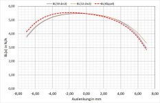
In different measurements between 18DS115 and 21DS115, it appears that the Bl on 18DS115 falls sooner than on the 21DS115, despite the fact that the 18DS115 has 4mm longer voice coil than 21DS115.
I am afraid that for that reason I cannot rely on such data, and need a set of very different ones. Probably mechanical and acoustical THD at Xmax through frequency range. That would be more telling about how the driver performs, and only in case of troubleshooting performance issue, this data might help to figure out the underlying issue.
Just want more braincells to fire up, there is no intention of tearing down these professional results. This is my reasoning for my way of working, feel free to ignore my concerns.
Without according Kms comparison and physical measurement of the coil offset on potentially fairly centered (we rather need decentered) driver, we still cannot tell much.
Here is the issue depicted:
https://audioxpress.com/article/Test-Bench-BMS-18S450-18-Pro-Sound-Subwoofer
The driver seems to behave "very centered" at Xmax with Klippel measurement at large signal input, but given the data and all curves, we see that it is 4.2mm decentered at rest position in reality.
With the DC measurement approach, If we imagine that the suspension was symmetric, we would still see the decentering up to Xmax, although lowered by exponential function of the suspension stiffness. We would theoretically still get offset, but with Klippel we get "zero". This possible discrepancy bugs me about the different approaches. Here, the DC offset approach of Dayton or mine (WNted to go that way myself, just mechanically with force, to determine the rest).
On the other side with Klippel:
In different measurements between 18DS115 and 21DS115, it appears that the Bl on 18DS115 falls sooner than on the 21DS115, despite the fact that the 18DS115 has 4mm longer voice coil than 21DS115.
I am afraid that for that reason I cannot rely on such data, and need a set of very different ones. Probably mechanical and acoustical THD at Xmax through frequency range. That would be more telling about how the driver performs, and only in case of troubleshooting performance issue, this data might help to figure out the underlying issue.
Just want more braincells to fire up, there is no intention of tearing down these professional results. This is my reasoning for my way of working, feel free to ignore my concerns.
Sure, but you're aware that the graphs we are looking at don't just look at the voice coil, but only how symmetrical the BL curve is?despite the fact that the 18DS115 has 4mm longer voice coil than 21DS115.
Meaning how well the other mechanical parts, like steel parts, are made.
Or in other words, the voice coil could be perfect, but if the design of the motor itself isn't symmetrical, we still end up with an asymmetrical curve.
@Kravchenko_Audio can probably tell you all about it, since he has been designing drivers for a very long time! 🙂
To be honest, the BL measurements are the easiest in this regard, as long as the reluctance is being taken care off.
The biggest rabbit hole is the compliance, by far.
Anyone who knows how excursion vs stiffness works, knows that the the default Kms(x) don't tell the whole story (at all).
Not taken any instability issues into consideration.
This is true. Plus you end up with a built in source of odd harmonic distortion. It is audible. Getting full linearity of the B field versus the voicecoil takes me the most time when designing an underhung. It is a little easier in an overhung motor. But the prevalent motor typologies that you see regularly are stronger on the pull than on the push of the driver.but if the design of the motor itself isn't symmetrical, we still end up with an asymmetrical curve.
Sure, but you supposedly should not have more motor force drop on "both sides" despite "the same motor" and longer voice coil. That does not add up.Sure, but you're aware that the graphs we are looking at don't just look at the voice coil, but only how symmetrical the BL curve is?
Meaning how well the other mechanical parts, like steel parts, are made.
Or in other words, the voice coil could be perfect, but if the design of the motor itself isn't symmetrical, we still end up with an asymmetrical curve.
Anyways I have new plan. Will make a static measurememt setup using two methods (albeit on just -X range with one of these). Force method, electrical DC current offset method.
Will borrow a B&C speakers driver that will be available and B&C (probably kindly as always) provide Klippel data. Will compare all three methods to show me better picture of the issue. Then I hope things will be clearer.
It still will not solve for variable DC offset and distortion through usable frequency range, though preliminary tests show that mostly distortion rises with falling frequency even at constant cone excursion if all works as should, cone is not folding on itself and such. Though we can't measure cone folding at dustcap position very well either. It looks to me like the endgame will always be the THD measurement, and underlying (Klippel) data will be just for precise identification of the "culprit".
- Home
- Loudspeakers
- Subwoofers
- Is there a DIY technique to measure the BL curve of a woofer?