A very bad idea to connect two voltage sources in parallel. Take off the short circuit and do not fool your head!
E.g. remove the connection E1+in to E1+out 🙂
P.s. I see I'm a bit late 🙂 sorry bin away a few days 🙂
Hi Guys everything oke?.
I have a small question, how can I get symetric output voltage from a Dflop getting from digital?, normally I do not need that but because I put a square into a triangle I get error except when use a cap, but then it takes forever before the stable voltages are reached, it starts nigative and slowly when cap charges get into normal plus and minus 1.5 volts triangle. Or is there a way in ltspice to get a stable point right away?.
Thanks.
For a capacitor you can add
ic=1.5
after the capacitance and this means the simulation will start with the capacitor having a 1.5V charge (the Initial Condition). So you can run a simulation until it stabilizes, record the capacitor charge and use that as the initial condition.
ic=1.5
after the capacitance and this means the simulation will start with the capacitor having a 1.5V charge (the Initial Condition). So you can run a simulation until it stabilizes, record the capacitor charge and use that as the initial condition.
Thanks mate, I get it,.
I get it not mate, how to set that up but I do nothing.
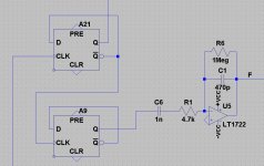
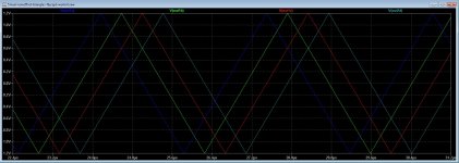
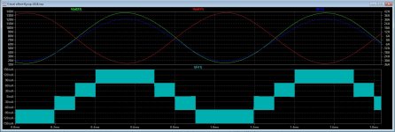
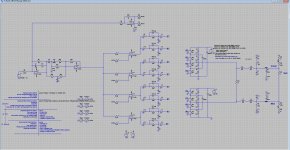
Here is the square to triangle, x 4 for multilevel class D inverter.
This did not work properly, better is four voltage sources who make the triangles.
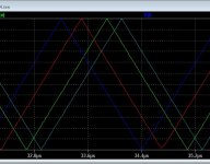
However I get not excactly the proper 90 degree distances, somebody see maybe a mistake somewhere, I did 300n, 600n, 900n has to keep the triangles the same distance.
thanks.
I get it not mate, how to set that up but I do nothing.
Here is the square to triangle, x 4 for multilevel class D inverter.
This did not work properly, better is four voltage sources who make the triangles.
However I get not excactly the proper 90 degree distances, somebody see maybe a mistake somewhere, I did 300n, 600n, 900n has to keep the triangles the same distance.
thanks.
Attachments
Try this. The simtime variable can be the same as the variable used for the .tran command. This is because setting the voltage to zero still causes integration errors at the triangle tips, unless the source is delayed out of the simulation timeframe, so to turn it off the delay is set to the simulation time.
Symmetry can be adjusted.
This is the most accurate and fast triangle generator I know of, because it uses hardcoded SPICE primitives. But the phase cannot be set below 90 degrees.
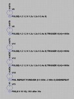
I updated it to be a bit more comprehensive with multiple input options. You can specify the shape using different combinations of risetime, frequency, symmetry and delay.
Symmetry can be adjusted.
This is the most accurate and fast triangle generator I know of, because it uses hardcoded SPICE primitives. But the phase cannot be set below 90 degrees.
I updated it to be a bit more comprehensive with multiple input options. You can specify the shape using different combinations of risetime, frequency, symmetry and delay.
Attachments
Thanks
I need 4 shifted triangles, I did it with Dflop and opamp but simtime gets long. Your solution is very nice but I am not a ltspice guru, I have not very much knowledge about that program.
Dflops give 90 degree shifts, work fine for this work, or a programmable chip.
I need 4 shifted triangles, I did it with Dflop and opamp but simtime gets long. Your solution is very nice but I am not a ltspice guru, I have not very much knowledge about that program.
Dflops give 90 degree shifts, work fine for this work, or a programmable chip.
Attachments

Last edited:
Thanks I will try, see that quality of triangle is better also, I have sometimes strange top voltages.You just have to use multiple sources and add the correct amount of delay per wavelength.
It does work this way however when change the tekst it jumps in one row making it a mess, I do afcourse something wrong.You just have to use multiple sources and add the correct amount of delay per wavelength.
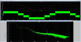
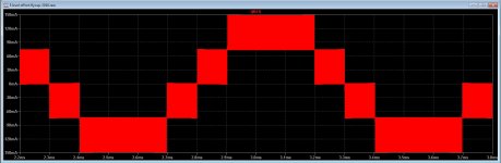
Here is the plot of the 5 level class d see 300 Khz become a lot higher, your triangels are much more precise as what I had.
But I have received the parts, after weeks, so I go on with the circlotron autobias.
Thanks mate for the help.
I updated it to be a bit more comprehensive with multiple input options. You can specify the shape using different combinations of risetime, frequency, symmetry and delay.
Have change the degrees, and it works like a charm, was for the 8 level class D postfeedback test, did nicely multiply carrier by 8, running on 50 khz, simulation now is a lot faster...
Today I get parts circlotron so I go on with that, class D is for later.
thanks for the good help..
Hi keantoken.
I have copy and past some parts from another schematic, however when I do this the parts do not work anymore, delete them and put new ones from library and it works again, it is a buffer part from digital in parts library.
Part is A5 buffer, it is just a part of dead time.
regards
Attachments


See if the original schematic has .lib or .inc lines. Usually when this happens there is a library file in the original schematic directory and you need to copy it to the new folder and add the .inc/.lib lines.
That is the generic case at any rate. I would need more information if that is not the case.
That is the generic case at any rate. I would need more information if that is not the case.
No that is not needed, I can just place a digital part and it works, only when copy them from a other schematic into mine, it does not work anymore, no signal, delete them and put new on schematig and it works again, maybe a bug.
It is not that a problem.
It is not that a problem.
Could, mooly or other people help, ltspice simulation of the (old) qsc usa 850.
It would great if the oscope shots in service manual would be similar to ltspice ones and the amp tuning would result even to some degree as in service manual.
It would great if the oscope shots in service manual would be similar to ltspice ones and the amp tuning would result even to some degree as in service manual.
Probably, but you can't simulate a qsc 850 usa to the (real one). So when time and me allows after couple months I'll repair the old qsc.1 channel broken. Drivers, bjt toast + to3 also. 1 cap at diode bridge.
When I find(( intrest, (fun)) . May take a couple months maybe longer. Prediction uncertain.
When I find(( intrest, (fun)) . May take a couple months maybe longer. Prediction uncertain.
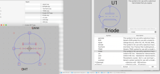
I am struggling to add a device symbol variant: I made a DHT.asy, placed it in the appropriate /misc folder, but it does not appear in my list. The path in the selection box is the same as where I placed it, but only the triode.asy shows up.
- Macos; LTSpice Build Nov 29 2018; I unhid the file in the appl folder and it is there
What am I doing wrong?
-------------------------------
Oops I found out - have to restart LTSpice to clear the buffers. 😱
- Macos; LTSpice Build Nov 29 2018; I unhid the file in the appl folder and it is there
What am I doing wrong?
-------------------------------
Oops I found out - have to restart LTSpice to clear the buffers. 😱
Attachments
Last edited:
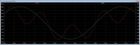
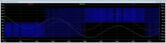
I get a very strange output voltage from a 5 level class d, de current is very nice sinus (green) but voltage itself on output is messy, (red) is this a common mode problem? the input triangels are 90 degree fase shifted. Can LTspice do sim these right?
never mind, I did find it, the first has a 180 degree shifted audio signal, now I have put that to a single imput signal and four 90 degree fase shifted triangles, did invert one side of the output stage and it works now., iy is quite tricky
regards
never mind, I did find it, the first has a 180 degree shifted audio signal, now I have put that to a single imput signal and four 90 degree fase shifted triangles, did invert one side of the output stage and it works now., iy is quite tricky
regards
Attachments
Last edited:
I am struggling to add a device symbol variant: I made a DHT.asy, placed it in the appropriate /misc folder, but it does not appear in my list. The path in the selection box is the same as where I placed it, but only the triode.asy shows up.
- Macos; LTSpice Build Nov 29 2018; I unhid the file in the appl folder and it is there
What am I doing wrong?
-------------------------------
Oops I found out - have to restart LTSpice to clear the buffers. 😱
You can search on google for tubes.lib I have these but to big to post.
Wel it is late here but i did try to use a feedback.
Wat I now discover is that the problems arrive if I set startup uic on I get respons as in pic 1, when set startup uic off in pic 1 I get as in pic 2 that is the good respons.
Can someone explane that?. Maybe it is normal behavior but do I not now why, it is important the sims go wel otherwise it is time consuming until I dixcover it are the settings who are wrong.
thanks.
Attachments

Last edited:
I made my triangle generator so that the initial operating point of the triangle source was always 0. Other triangle sources start at the upper or lower level which causes DC drift if for instance simulating an amplifier. If you want to try it without the operating point adjustment you can disable the Vtop sources.
Other than that, without seeing the simulation I would have no idea.
BTW, where do you get your info for simulating class D?
Other than that, without seeing the simulation I would have no idea.
BTW, where do you get your info for simulating class D?
Last edited:
Is this maybe a reason that the simulation go wrong sometimes and then it does work, maybe because of the sources you mention?.
I have the info from google, I use the multilevel inverter info everywhere seen there, and a new version of postfeedback but need to calculate for used low pass.
What simulation you need to see, the schematic?
regards
I have the info from google, I use the multilevel inverter info everywhere seen there, and a new version of postfeedback but need to calculate for used low pass.
What simulation you need to see, the schematic?
regards
- Home
- Design & Build
- Software Tools
- Installing and using LTspice IV (now including LTXVII), From beginner to advanced