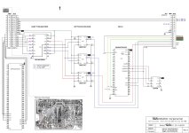
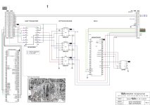
Hi, I ordered 2 MC74HC595 today, to see if its replacement can help. My thought is that the values measured - with the scope - on 3 outputs of this shift register do not look like they should, see schematics. The optocouplers seem to be working correctly, both inputs and outputs, as far as I can judge after trials.
Here is the latest version of it.
Here is the latest version of it.
Attachments
Hello everyone, I just replaced the shift register 74HC595 with no better result...
A few things remain unclear to me:
Good day!
A few things remain unclear to me:
- when I measure voltage on pin 1 and 2 (shift register), either I've got 0V or 5V depending on what I'm doing with the remote, BUT the voltage remains the same as long as I don't press again a button on the remote. As if it keeps memory of it as long I didn't press the button another time. I don't see clearly why. Something related with the latch clock behavior? I didn't test all outputs, I'll do it more seriously this afternoon.
- I don't see any decoupling capacitor on that IC, against usual practice. Then I tried to put temporarily a 10nF ceramic on ground and Vcc to see if something would change, but no. Maybe I should try a 0.1µF. Or is it not recommended? I can't think that Wadia has forgotten to put one here's there are decoupling SMD caps everywhere...
- I'm waiting for 3 optocouplers (and a real Texas Instruments 74HC595 too) from Mouser next Monday. Maybe I should prepare DIP-8 supports in advance.
Good day!
Attachments
IT WORKS!!!!!
IT WORKS. IT WORKS.
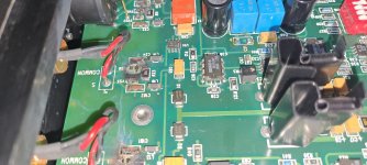
I've replaced the 3 optocouplers (U42, U43, U44 on the schematics) and it works. I didn't soldered them, I chose to plug them on DIP-8 good quality sockets. As I did for the shift register.
I had some difficulties to unsolder the old ones, but I could finally make it and keep the PCB in good (enough) shape. Vias are really small so it's not super easy. That's the kind of moment when I don't regret having a Metcal desoldering station!

I'll post more pictures later after reassembling the rest of the feet and screws etc.
Once again, thanks @purer for your suggestions! You were absolutely right.
Good evening everyone.
IT WORKS. IT WORKS.
I've replaced the 3 optocouplers (U42, U43, U44 on the schematics) and it works. I didn't soldered them, I chose to plug them on DIP-8 good quality sockets. As I did for the shift register.
I had some difficulties to unsolder the old ones, but I could finally make it and keep the PCB in good (enough) shape. Vias are really small so it's not super easy. That's the kind of moment when I don't regret having a Metcal desoldering station!
I'll post more pictures later after reassembling the rest of the feet and screws etc.
Once again, thanks @purer for your suggestions! You were absolutely right.
Good evening everyone.

Glad to hear the results of WADIA successful repair. I also have a suggestion, replace the old capacitor, it is thirty years old. Compared with the use time of the capacitor, it is a bit too long.
Thanks @purer, I'm (very) glad too!
I replaced the 1Ω 2W resistor near the 5V supply first, not that it was bad, but to put it away from the board as it runs quite hot.
I bought the caps to replace them but didn't do it yet. I measured ESR of the three "big ones" and it was good so it's not an emergency I think. I wanted to replace all the small caps (47, 100µF) near to the 4 PCM1702. I've seen on pictures of the 861 that these caps were organic polymer caps (vs EL aluminium standard caps on the W16) and I think it's a better choice. I'll probably buy a bunch of them and do that work later.
Have a good day!
I have one in bits on my bench, so I will take a macro shot tomorrow during daylight.
If you don't get them, please pm me tomorrow
Roman
If you don't get them, please pm me tomorrow
Roman

Nawet nie wiesz, jak bardzo jestem Ci wdzięczny. W serwisie powiedziano mi, że naprawa będzie kosztować 9 000 zł. To około 2300 dolarów.

English please.
You don't even know how grateful I am to you. At the service I was told that the repair would cost 9,000 PLN. That's about $2300.
You don't even know how grateful I am to you. At the service I was told that the repair would cost 9,000 PLN. That's about $2300.
My Wadia 16 looks nothing like it.
I have not opened the other one, but I am sure the other one - judging from old pictures I have looks exactly the same but different to yours.
Sent you a pm
I have not opened the other one, but I am sure the other one - judging from old pictures I have looks exactly the same but different to yours.
Sent you a pm
I'm rather sure that mine is just like yours @rockeater, even if I've got no precise picture of that specific area. What I'd recommend to @tolas123 is to have a look at the schematics (I must have put all documents I have online, just a small search would lead you to it) and have a look at this part of the schema. I'll have a look myself later when I got a little more time.
Hi @tolas123 , is it the same schema you've got than the one I attach? Seems to me I can read it and link to your picture, as far as I can see? I'm not certain since I can't read the components very well, but it looks like it, or am I wrong?
If necessary, I've got the same one for left analog circuit. Let me know.
If necessary, I've got the same one for left analog circuit. Let me know.
Attachments
Hi. Thank you very much, I read it. This is a diode with the marking; MMBZ15VOL T1
The only problem is that I can't find it with this marking.
In my opinion it is a 15V zener diode. I found a similar one but with three leads.
These diodes connect to the housing.
The only problem is that I can't find it with this marking.
In my opinion it is a 15V zener diode. I found a similar one but with three leads.
These diodes connect to the housing.
- Home
- Source & Line
- Digital Source
- I have Wadia 16 and Krell Schematics