I have talked with the technician and it said that never happened to him this problem.It would be interesting to have some information from him, certainly. This problem must not be common but it seems we are two facing it. Thanks if you can ask!
good evening
But it told me that can be the IC o check the voltage to that IC, check for solder crack,etc…
I have also see a guy that made a fantastic work in a W 16 that encountered some bad IC and solder crack’s in the servo board.
https://audiodripper.jp/wadia-16-restore/amp
Thanks Pedro, that seems to be a good lead? I encountered (and repaired) crack solder joints on so many "vintage" machines that I (should) could check the servo board, this is a (very) good option to start with. I thought Wadia would not be concerned by this problem, but the servo is not Wadia, it's Teac made. Which is not as bad as Luxman or Marantz pieces made in the eighties that I know, but who knows? After 25 years or more, it's not impossible, even if the PCB is solidly screwed and not as flexible as large PCBs held by just 3 or 4 screws...
If erdemeter has his own W16 on the bench, maybe a quick check on the Servo PCB's solder side with binoculars could tell us more. I'll try to do that soon myself.
If erdemeter has his own W16 on the bench, maybe a quick check on the Servo PCB's solder side with binoculars could tell us more. I'll try to do that soon myself.
Sorry for late reply. I somehow stopped getting notifications from DIY AUdio.Rockeater thank you for your attention.
Was your 16 same problem with mine(work fine but no servo commands from remote or front panel)
What was the problem exactly of your 16 before reverse the flexible ribbon cable?
The previous owner tampered with it and wrote something on the ribbons. I think it's the same fault with your own 16.
Now, I'm worried that if I reverse the strip from the servo card to the dac card, there will be damage to the device. Also, if the ribbon cable is inserted upside down, Isn't it interesting that the device is still working?
How can I find the correct connection positions for flexible ribbon cables.
Can someone help me ?
No, my problems were different.
To start with, the tray did not work but it was fixed by mechanical service (replacing of belts and cleaning of limit switches).
After that it worked well as transport but had no analogue output.
Ribbon reversing fixed this (the one from servo board to the top board, from where it goes to display via some buffers I think).
The reason it still worked and did not blow anything, was a good Wadia design.
Out of 15 traces on the ribbon, the supply was on trace 8 - the middle one. So regardless how you inserted it, the volts were still on the same pin.
All this above is from memory.
For more accurate details, have a look at the video (the earlier one) on my uTube channel hear-net-au.
Search for Wadia 16, because there are hundreds of videos I shot of Cd player repairs there:
https://www.youtube.com/c/hearnetau/videos
Cheers
Roman

Hi, I also own Wadia16 and unfortunately I am the owner of similar and other problems. I was very grateful for the circuit diagram.Hi pspentax, I've got a few of them, allow me to send you the docs via PM or I'll post them in the thread? tell me. Cheers from France.
313rifdotgmail.co
Cheers from Spain.
Hi RIF13, I just saw your message and sent an email with the files.
On my side, I didn't take the necessary time to investigate on mine, sorry. Fortunately I've got a WT3200 to replace. And a Krell 300 if necessary. Hope to attempt a fix soon.
On my side, I didn't take the necessary time to investigate on mine, sorry. Fortunately I've got a WT3200 to replace. And a Krell 300 if necessary. Hope to attempt a fix soon.
Anyone out there with the Service Manual for Wadia 860/861?
I am converting 120V AC unit from US to an European 220V AC one and have (I think) worked out how to do it, but want to go a step further and make it 240V AC which we have here in Australia.
Alternatively, a user with 230V or 240V AC unit could help by quickly buzzing the input board with a multimeter.
I will post my findings here, once I make a proper drawing.
Hi everybody, it's a long time I haven't been writing on this thread. I reopened the beast a few days ago to understand what could be the problem. My problem. Reminder: it works but NO disk control servo command (faceplate: open/close & play; remote: id°+ skip/FF/FR...) works.... That means that I'm obliged to play the same disc forever, from start to the end, as soon as I put the player on. Of course, if I want to play another disc, I can. I just have to open the W16, unscrew the 4 screws that hold the clamp, take the disc out and put another one, screw again the 4 screws (even not necessary...), put off/on the player and that's it. Easy but long and not really user-friendly.
So I've been looking for a solution for a long time... without real success, and despite good ideas from fellows here...
Last week I took the servo board out (Teac) to watch thoroughly every solder point. I reflowed some of them which were good at continuity test but looked poor. I replaced all EL caps (all of them). Most of them were good at ESR meter (most), but while I was here, and with the low cost of the 40 or so caps, I found it useful anyway. But it didn't change ANYTHING in the problem.
Then I went to imagine (!) that the DAC board (the Wadia one, the first one you see when you open the player) could be concerned by the issue, as one flat ribbon cable links the faceplate board with the DAC board. I started to investigate voltage measures around the MC68HC705C8CP IC which is obviously connected with the flat ribbon connector. I have 5V on pins 17 and 18 (4,93V precisely), which falls down to 0V when I press the Open/Close or Play buttons, so something happens (at least, at last). On the other hand, nothing measurable with the remote control... But there is something to look at, now.
So I follow the copper, and I notice that all measures on the MC74HC595AN IC (U45 on the Wadia schematics, a shift register CMOS) showed a decrease of the voltages as soon as I plugged the probe (DMM or oscilloscope). Impossible to get a stable value. I'm no expert nor electronics engineer, so it looked strange to me because I couldn't understand what was going on. Don't have sufficient knowledge. But I suspected that some "wrong grounding" was "taking the current" out of the IC... (my words, sorry).
Then I went to investigate this IC's pin #8 (GND) and by testing continuity with a known ground, saw that there was no continuity between them. This is not what I could expect. I add that pins #8 & 13 are connected via a track on the PCB.
Now I'm wondering what to think and which signals to track and where? I'll go on tomorrow, just wanted to post that as a track of my investigations of the day 😉
Attachments


Last edited:
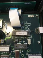
On the 3rd pic the ribbon is not inserted properly into the display board (it is crooked).
Also check, if the ribbon from the Wadia board (top) going to the Teac servo board is not folded in any way. If it is, then it is inserted the wrong way round.
If in doubt, check with continuity tester whether components from both boards are connected as per diagram.
Middle pin on that ribbon supplies voltage but wrong insertion at either end would move ground, which is what appears to be your problem.
I am sure you have done all this, but I write it "just in case".
Maybe also check both ribbons for continuity of each trace end to end.
Hi @rockeater, thanks for your input.
The picture doesn't show really how it is when in function, it's just meant to figure how it is plugged. As you know already, the problem occurred one day as nothing had been touched or even opened. Since that day, I tried different options to figure out where the problem could be coming from, and of course, I plugged/unplugged several times all ribbon cables to take the boards out and have a more accurate look at them. I remember you encountered that problem of a ribbon cable reverse plugged and that you solved it by putting it in the correct position. Unfortunately, it doesn't seem as obvious and simple on my player.
The ribbon cables have been checked, all of them, and I plug them as they should before attempting any measure or signal tracking.
It seems that (at least part of) the problem is (could be) related with this "non-continuity" that I tested between the U45 IC's pin #8 (GND) and the actual GND on the circuit. Whether it is a PCB track which is broken somewhere or a fail in the IC itself, I don't know at present. It is written on the board that it is a 4-layer board, which could make it more complicated to investigate, even if GND tracks are usually visible and large enough not to be "sandwiched" between outside faces of the board, but of course I could be wrong. But if the IC itself was broken-down, then it wouldn't question the integrity of the GND track and I could check continuity between the external pin and another GND on the board, as I can track on all other ICs...
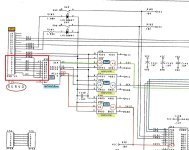
So before I unsolder that U45, I will try to see on the schematics how all that is theoritically assembled. Even if the schematics I have posted is not absolutely similar to my own board. There are some differences which are probably due to the player different versions.
The picture doesn't show really how it is when in function, it's just meant to figure how it is plugged. As you know already, the problem occurred one day as nothing had been touched or even opened. Since that day, I tried different options to figure out where the problem could be coming from, and of course, I plugged/unplugged several times all ribbon cables to take the boards out and have a more accurate look at them. I remember you encountered that problem of a ribbon cable reverse plugged and that you solved it by putting it in the correct position. Unfortunately, it doesn't seem as obvious and simple on my player.
The ribbon cables have been checked, all of them, and I plug them as they should before attempting any measure or signal tracking.
It seems that (at least part of) the problem is (could be) related with this "non-continuity" that I tested between the U45 IC's pin #8 (GND) and the actual GND on the circuit. Whether it is a PCB track which is broken somewhere or a fail in the IC itself, I don't know at present. It is written on the board that it is a 4-layer board, which could make it more complicated to investigate, even if GND tracks are usually visible and large enough not to be "sandwiched" between outside faces of the board, but of course I could be wrong. But if the IC itself was broken-down, then it wouldn't question the integrity of the GND track and I could check continuity between the external pin and another GND on the board, as I can track on all other ICs...
So before I unsolder that U45, I will try to see on the schematics how all that is theoritically assembled. Even if the schematics I have posted is not absolutely similar to my own board. There are some differences which are probably due to the player different versions.
Of course, there was an explanation... There are 2 different grounds, one which must refer to the DAC board and a second one, GND2, which probably refers to the servo board... visible pin#9 on JP11, the connector which goes to the servo. And pins #8 and 13 of the shift register IC (MC74HC595AN) are well connected to this GND2.

Now I need to plug a connector to the relative servo board ground and take it as a reference for measuring the voltages on ICs related to this ground to check.
My player's version differs slightly from the only schema I've got, so I'm still trying to understand from this schematics which signals I can expect and where...
Hello!
The control of WADIA 16 should be different from the CD servo of a system. I think your failure should be a problem with the CD motherboard.
The control of WADIA 16 should be different from the CD servo of a system. I think your failure should be a problem with the CD motherboard.
When you can control the volume of decoding and so on, you can assume that the MCU is working properly.
Thanks @purer for this contribution. I'm just into discovering that my scope can trace SPI signals and how I can do it. All new for me, as I'm no engineer and not fluent (at all) in digital interfaces and how all that is working. Plus, the schematics I've got are from a different version of my player, and not all ICs are the same, even if I assume they accomplish the same work.
What I can say at present is:
If it can be useful, and in order to help me to understand how all that should be working, I can post here some pictures (scope signal) and the modified schematics as I have drawn from what I understand...
Thank you all readers!
What I can say at present is:
- the remote control does have an effect on some functions (volume, display on/off and some few others)
- the same remote doesn't operate any disc function (play, skip, index, or open/close)
- the 2 buttons (play and open/close) on the faceplate don't work
- I can see the clock signal and the MOSI/MISO traces perfectly synchronized on the scope
- It does something on these signals if I press the buttons on the remote/faceplate, but as I don't really know what is the "order" of ICs on the signal route, it's difficult for me at this time to know if there is a place where I must look for a signal (don't know if I'm clear enough on this)
If it can be useful, and in order to help me to understand how all that should be working, I can post here some pictures (scope signal) and the modified schematics as I have drawn from what I understand...
Thank you all readers!
Last edited:
No thanks. Help each other.
Remote control When using the action, it proves that WADIA's motherboard is intact, and the TEAC read is unresponsive, which only proves that it is problematic.
There is no need to complicate the problem. Remote control can be controlled without having to worry about communication such as I2C.
1 Check whether the connection cable between the WADIA motherboard and the TEAC motherboard is broken
2 Check whether the signal of HPCL-7100 2 6 pins is the same. If it is different, you can consider whether the HPCL7100 is damaged.
@purer let me regardless thank you 😉
I think you could be right, I'm finishing to draw the (simplified) schematics of the version I own, which is rather different from the schematics I've got, and I'll check once more specifically on the place you mention. I guess you are talking of U42 (on my board, could be U38 on the schematics I've got), a HCPL7100 opto-coupler which conveys data from the MC68HC705C8PC MCU to the MC74HC595AN serial/parallel shift register (and the servo Teac Board).
I'm still in drawing in order to be able to take correct measures, with the real components and actual routes, since I've redraw all of them between all concerned components (tested continuity).
I'll let you know the result, but I'm more confident after your explanation, since it would be the simplest and more coherent response to the problem.
By the way, which version do you own yourself?
Good evening!
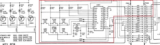
Here is what I could do with a quick work to represent the part that concerns disc control commands (both faceplate buttons and remote) on that version of the Wadia 16. Even if I'm not familiar with that exercise, I had some pleasure doing it 😉
I hope not making mistakes and I will probably improve it soon. If it can help the community I'll be glad.

I hope not making mistakes and I will probably improve it soon. If it can help the community I'll be glad.
Hello!
Today I read the TEAC 10N service manual carefully, and I think the focus should be on the HPCL7101 and HC595, which is the command interface for CD keyboard control. So what you should do now is to find a new HPCL7101 to replace it. I used to use WADIA9 as an I2S audio isolator with HPCL7101. Noise often occurs because it is damaged.
Today I read the TEAC 10N service manual carefully, and I think the focus should be on the HPCL7101 and HC595, which is the command interface for CD keyboard control. So what you should do now is to find a new HPCL7101 to replace it. I used to use WADIA9 as an I2S audio isolator with HPCL7101. Noise often occurs because it is damaged.
Attachments
I tested the 3 optocouplers (diode function) and the 3 of them show exactly the sale values (static measures of course). On the other hand, the MC74HC595 shows a strange 0V value out of pin#6, which I've got to investigate more precisely.
I add the last version of my redrawn circuit, with DMM voltage values that I could take. On the O-scope, I can see the bits almost everywhere but can't say right now if they are coherent. I'lm not fluent enough with it and SPI circuits testing... yet. But I make some slow progress every day I work on it. 😉
And as HCPL-7100 are not easy to find, I thought I could replace them (if needed) with these ones that seem very similar.
Attachments
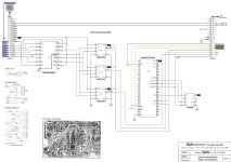
I can add that I must check more precisely VDD1 on U44 pin#1, because it seems to be at the low limit for +V input as described on the data sheet (4,5V minimum). I measured it at around 4,6V but it could be slightly different (more or less). Is the SMD capacitor (#143) responsible for that in any way, I don't know, but I could test it too.
By the way, I've got to look for a 50 MBd (vs 15MBd) data rate optocoupler as they are 7101 and not 7100 (have to correct this on the schematics). Unsure it is important... but better be correct. Like these ones.
By the way, I've got to look for a 50 MBd (vs 15MBd) data rate optocoupler as they are 7101 and not 7100 (have to correct this on the schematics). Unsure it is important... but better be correct. Like these ones.
Attachments
Last edited:
- Home
- Source & Line
- Digital Source
- I have Wadia 16 and Krell Schematics