Is (digital) clipping in the DLCP a concern when applying a boost filter?
If said boost filter can result that the signal after all filters are applied clips then of course. So say if you have a boost filter at 100 hz and lower at +6 dB and then a global -6 dB then they will cancel and you will not have to worry about clipping.
If I remember correctly you shuldn't have to worry about in which order you do the filters as the DSP works internally at higher than 24 bit precision.
in the spirit of full disclosure, I use the NC400 directly coupled into a compression driver, I know what the replacement diaphragm costs. The drive for the NC400 is ac coupled.
its DIY
Cheers
Alan
its DIY
Cheers
Alan
If said boost filter can result that the signal after all filters are applied clips then of course. So say if you have a boost filter at 100 hz and lower at +6 dB and then a global -6 dB then they will cancel and you will not have to worry about clipping.
If I remember correctly you shuldn't have to worry about in which order you do the filters as the DSP works internally at higher than 24 bit precision.
So, if I understand you correctly, in filter designer the blue line should never go above 0 db after all filters and gain have been applied. I find it a bit strange that this is not stated in the manual.
While waiting for DLCP, I have downloaded HFD 4.5 and trying to get familiar with it (so at this point there is no DLCP module connected).
HFD recognized my Scarlett2i2 and its driver under "tools>asio prefernces". Sample rate on both 44.1Khz. However after "take measurement" command, it shows "error: invalid floatingpoint number".
Would anybody help clarify? Can HFD make measurements at all without DLCP connected?
HFD recognized my Scarlett2i2 and its driver under "tools>asio prefernces". Sample rate on both 44.1Khz. However after "take measurement" command, it shows "error: invalid floatingpoint number".
Would anybody help clarify? Can HFD make measurements at all without DLCP connected?
HFD can take measurements without a Hypex product connected.
Thanks DS23, I thought so. Will contact Hypex regarding the problem I encounter.
Hypex ISIS news?
The MP amp modules are now shipping however I've found no status info on the ISIS module that presumably replaces the current Hypex DSP products. Does anyone know if this is still in the works and if so is there is a timeframe for release? Thanks, Terry
The MP amp modules are now shipping however I've found no status info on the ISIS module that presumably replaces the current Hypex DSP products. Does anyone know if this is still in the works and if so is there is a timeframe for release? Thanks, Terry
This has happened to me as well for no obvious reason.
A reinstall of the firmware fixed it
Thanks! I will look into it and try to reinstall firmware deffinitely. I'm quite affraid doing it, though.
BTW, I have 100% proven method for UMIK-1 USB mic users how to import REW measurements directly to Hfd software and how to work on REW impulse response inside Hfd. Works like a charm. 🙂 Anyone interested?
Last edited:
Reinstalling firmware is a painless process. Controller firmware is a bit more tricky if using two modules, but method have been discussed here earlier.
The MP amp modules are now shipping however I've found no status info on the ISIS module that presumably replaces the current Hypex DSP products. Does anyone know if this is still in the works and if so is there is a timeframe for release? Thanks, Terry
The 2by4 ( isis) is oem only and is not supported in HFD.
ds23man, thank you for your rapid reply. I've heard it is OEM only, however two questions regardless: is it shipping or is there a timeframe; what is HFD? Sorry for the last, I'm rather new here and the acronym's meaning is eluding me. thanks, Terry btw, Merry Christmas!
I am curious why only one person asked me about how to import REW measurements to the HFD software? Do you all already know how to do it and I missed something? 🙂
Here you are:
1. Use HFD 4.4 or later.
2. Make sure both REW and HFD are using the same sampling rate, let it be fs=44100 Hz.
3. If you are using DLCP as DAC during measurement clear measured channel of DLCP to flat. Don't forget uploading it to DLCP... 😉
4. Set measurement frequency range in REW: It should be always from 10 Hz up to 0,5 fs (22050 Hz in our case). It means that also tweeters should be measured from 10 Hz. Single short sweep at low power shouldn't make any harm to tweeters. Using any passive filter between amplifier and driver will alter frequency and phase response unfortunately.
5. Take an impulse response measurement of your loudspeaker with REW as always, using your UMIK-1 USB mic. REW IR window settings are not relevant.
6. In REW: Go to File -> Export -> Impulse Response as text. Name it like you want. You will get plain *txt file.
7. Open this file with Windows' Notepad. You will see several lines of text with information added by REW: Date, level, settings etc. Below this information full impulse response will be described and it will look something like this:
"4.5116394E-8
3.661903E-7
6.5142535E-7
7.7259074E-7
2.2867698E-7
1.4967445E-6
1.6226693E-7
-2.331628E-6
2.1714827E-6
-2.3316557E-6
..."
8. Delete all REW-related information from the beginning and leave only lines with bare impulse response description.
9. In Notepad: Go to File-> Save as...->
10. Change file type from *txt into *all files.
11. Add .dat extension to your file name and hit save.
12. You will get *dat file which is now readable by HFD.
13. In HFD: on the bottom of program window, below filter's window you will find "Import" button. Click "Import" and open your *dat file in HFD! 🙂
This impulse response is complete. It means that it is stripped of any REW-applied windowing and it will contain all sound reflections and room modes. You will need to truncate it inside HFD and apply proper smoothing in order to get usable near-field measurement to work with filters. This solution will not contain time-reference so you cannot set proper delays in DLCP channels.
Last edited:
Very nice, but..........
The simulation in HFD will not be correct due phase and timing errors.
And a Umic is useless in loudspeaker measurements because the dac and adc do not share the same clock.
Been there, done that.
I have stated this before:
Use the measurement tool in HFD with an asio soundcard.
The simulation in HFD will not be correct due phase and timing errors.
And a Umic is useless in loudspeaker measurements because the dac and adc do not share the same clock.
Been there, done that.
I have stated this before:
Use the measurement tool in HFD with an asio soundcard.
I understand time reference based limitations but this method is sufficient to equalise individual driver's frequencies and phase responses to flat. In reality this is not so important to fight for every microsecond of delays between x-over branches when you are using LR-4 crossovers applied on completely flat responses extending well over filters pass-bands. What do you mean as 'phase error' in minimum-phase systems? You can make simple crossovers also, even if you cannot possess all these analogue mics, audio interfaces, ASIO drivers etc. etc... 🙂
Last edited:
The simulation part in HFD will give strange results with the slightest timing errors between measurements. That is why I did a lot of testing during the design of HFD 4.x The measurement tool is so accurate that you can observe jitter problems in well known audio interfaces.
When I tested HFD with two seperate audio devices with asio (adc and dac), all simulations where all over the place.
When I tested HFD with two seperate audio devices with asio (adc and dac), all simulations where all over the place.
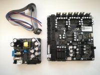
DLCP has arrived.. 🙂
Now it's time to do proper wiring.
I wont use official MOLEX connectors for outputs (I can't find them in my country) so I should find some nice way to connect all theese small parts..
Hope I'll do it before New Year so I'll post some pics during the progress.
Now it's time to do proper wiring.
I wont use official MOLEX connectors for outputs (I can't find them in my country) so I should find some nice way to connect all theese small parts..
Hope I'll do it before New Year so I'll post some pics during the progress.
Attachments
I understand time reference based limitations but this method is sufficient to equalise individual driver's frequencies and phase responses to flat. In reality this is not so important to fight for every microsecond of delays between x-over branches when you are using LR-4 crossovers applied on completely flat responses extending well over filters pass-bands. What do you mean as 'phase error' in minimum-phase systems? You can make simple crossovers also, even if you cannot possess all these analogue mics, audio interfaces, ASIO drivers etc. etc... 🙂
Maybe I have to clarify this. If you want to simulate, you will need to take the timing differences between the drivers in account. This is also named offset. The measurement tool in HFD will do this, imported measurements don't.
This has nothing to do with minimum phase (phase is related to the frequency respons).
ASIO4ALL will work with any WDM based audiodevice btw.
- Home
- Source & Line
- Digital Line Level
- Hypex DSP module(s)