Very nice build!Pics as promised! It sounds MUCH better off the batteries! A lot more quiet and better dynamics. I wired 2 power switches, one for AC power, one for DC power or both to charge. Complete with "breathing" power LED's! 😈
It is only a simulation, but I think the muuuccchh capacitance approach likely might not be the best option. Thinking about what PSU to use, I play with LTSpice and below are the two FFTs for "regular PSU" with 680,000u per rail vs. capacitance multiplier with 40,000u per rail. The top diagram is the FFT with CapMx at 10W RMS. I will definitely use that, as I will not go the battery lane 🙂 . CapMx looks like a good alternative to me.
What caps are you modeling? I have a mix of capacitors identical to the original article so a mix of ESR. I am running just over 1F per rail.
I am surprised at the 2nd / 3rd levels: high and the same. That means to me the input could (should ..) be biased differently. At least - in the sim.
I was surprised too. According to Hiraga's original article (and if I understand the French->English translation correctly), this is the typical THD of the FET cascode. He says to "somehow get rid of using the right BJTs", in his case 2SC1775 and 2SA872.I am surprised at the 2nd / 3rd levels: high and the same. That means to me the input could (should ..) be biased differently. At least - in the sim.
At least in the simulation, I am not able to get the desired falling THD behaviour reliably.
What do you think could be a way to bias differently to achieve it, @triode_al?
In any case, I will measure the THD before building an expensive PSU.
Edit: also, @triode_al , you said the level of the THD was high. The diagrams are for maximum power of the amp (or at least near), total below 0.1% depending on R values down to 0.02%. Is this unexpectedly high? What would be the expected THD at 12W on 4Ohms?
Any folks out there who have built a HLM close with non-Y-FETs who can provide a THD measurement of their builds?
This is easy to answer. It seems to be hard / impossible to build a HLM now with parts being near to original. If really the parts are key in getting a desirable THD scheme (which is audible), it makes perfect sense to try and understand what influences it.Why? LOL ... why do we get so hung up on how an amp measures vs how an amp sounds?
I am sure I can build a clone which does not sound completely awful. Still if I invest time and money (with a reasonable PSU, it will easily cost 700+ USD), I want a really good result.
BTW... listening to a DIY tube amp which sounds really great while writing this, but for that it was not too hard getting the parts as specified. Still I am curious and will give it a go on the test bench when I have the setup for doing THD measurements.
I built the Jim's Audio kit from eBay and used the Hiraga PS from the original article. I can tell you first off that I dislike solid-state amplifiers. My main amplifier is a Korneff 45SET. This gives the 45SET a run for it's money in dynamics and imaging which I attribute to the power supply when run off of battery due to non-existent PS noise and dynamics c/o ridiculous ability to produce current. The only thing lacking with respect to the tube amp is front-to-back soundstage. I build based on the input of others since audio analyzers are expensive and that THD is a misnomer as even harmonics raise the numbers giving false claims. I always say there is no "magic" even harmonic filter between a live musician and your ear. Having run sound in a previous life, I know what live instruments on a stage sound like and that is my benchmark. Go to a live concert then go home and compare. 😎
It's only money ... if you don't like it, sell it ... the Hiraga has a huge following so it would not be difficult to unload at the cost of parts. Labor is another story but chalk it up to experience.
It's only money ... if you don't like it, sell it ... the Hiraga has a huge following so it would not be difficult to unload at the cost of parts. Labor is another story but chalk it up to experience.

At 10watt the amp is near clipping; so then such behaviour of same 2nd 3rd might easily arrive.I was surprised too. According to Hiraga's original article (and if I understand the French->English translation correctly), this is the typical THD of the FET cascode. He says to "somehow get rid of using the right BJTs", in his case 2SC1775 and 2SA872.
At least in the simulation, I am not able to get the desired falling THD behaviour reliably.
What do you think could be a way to bias differently to achieve it, @triode_al?
In any case, I will measure the THD before building an expensive PSU.
Edit: also, @triode_al , you said the level of the THD was high. The diagrams are for maximum power of the amp (or at least near), total below 0.1% depending on R values down to 0.02%. Is this unexpectedly high? What would be the expected THD at 12W on 4Ohms?
How to force more 2nd? Well first of all, don't go beyond 3 watts. That loud enough mostly. --> show the distortion at 1 watt.
And somehow measure a real performance. e.g. with REW I heard it could be done. [I never did that]
- Then there might be some tricks to try to get more 2ndH/change the phase. But it requires some experimentation.
Yes, with sensitive speakers, a few watt is plenty. The tube amp I am currently using has only 2x7W, I suppose your SE has likely less.Well first of all, don't go beyond 3 watts. That loud enough mostly. --> show the distortion at 1 watt.
In the simulation it is getting worse with lower power, though. The attached FFT is for 1W RMS.
Using REW for this seems to be pretty easy. X has a nice guide for that here on this site: https://www.diyaudio.com/community/threads/howto-distortion-measurements-with-rew.338511/And somehow measure a real performance. e.g. with REW I heard it could be done. [I never did that]
I will definitely do that.
I am not after "adding" distortion, but I would like to get the odd harmonics be lower than the even.Then there might be some tricks to try to get more 2ndH/change the phase. But it requires some experimentation.
But again, simulation is just simulation and there may be errors (or just insufficient models). So not sure if the graph is at all realistic. I will just have the PCBs made, build it and measure.
Attachments
Last edited:
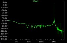
Need to correct myself. Had gotten lost in one of the variations I had played with. Similar PSU to before, 1W RMS looks promising.In the simulation it is getting worse with lower power, though. The attached FFT is for 1W RMS.
And BTW... this is still the Capacitance Multiplier PSU. I think this is really encouraging to be tested.
Attachments

Last edited:
So ... not a "Le Monstre" then? 🙄And BTW... this is still the Capacitance Multiplier PSU.
I think what makes it a Le Monstre is the amplifier circuit. That is as unchanged as possible under consideration that Y devices cannot be gotten anymore.So ... not a "Le Monstre" then? 🙄
Using a PSU, which is better than the original exhaustively C using one (the CapMx has almost no mains artefacts and in general very low noise floor), is fine for me. You mileage may vary.
I don't want to use the battery approach, so the CapMx looks like a great way of not needing.
Sorry, I disagree and this has been hashed over many times in this thread. The amp circuit itself is nothing special ... just a very minimalistic Class-A amp using parts available at the time of publishing. What makes it "Le Monstre" is the >1F capacitance per rail. Deviating from that is silly and there are MUCH better amp circuits out there (read Pass) if you want Class-A bliss. 🤷♂️
The battery source disconnects ALL possibilities of ground loops and 50/60Hz-induced hum.
Read the original article. The whole point of the project was to be able to supply current to satisfy all transients and then some.
The battery source disconnects ALL possibilities of ground loops and 50/60Hz-induced hum.
Read the original article. The whole point of the project was to be able to supply current to satisfy all transients and then some.
I know the name comes from the exhaustive C in the supply.Sorry, I disagree and this has been hashed over many times in this thread. The amp circuit itself is nothing special ... just a very minimalistic Class-A amp using parts available at the time of publishing. What makes it "Le Monstre" is the >1F capacitance per rail. Deviating from that is silly and there are MUCH better amp circuits out there (read Pass) if you want Class-A bliss. 🤷♂️
The battery source disconnects ALL possibilities of ground loops and 50/60Hz-induced hum.
Read the original article. The whole point of the project was to be able to supply current to satisfy all transients and then some.
The original PSU has two options, the exhaustive C PSU and battery. Battery is not an option for me. The CapMx seems to be definitely superior to the exhaustive C one in terms of mains supply artefacts.
You went another route, so what.
No ... the capacitance is the same regardless of battery or AC! Look at the schematic! It only bypasses 4 68kuF caps on battery vs AC.I know the name comes from the exhaustive C in the supply.
The original PSU has two options, the exhaustive C PSU and battery. Battery is not an option for me. The CapMx seems to be definitely superior to the exhaustive C one in terms of mains supply artefacts.
You went another route, so what.
I did not go another route, I built a Le Monstre.
AmenNo ... the capacitance is the same regardless of battery or AC! Look at the schematic! It only bypasses 4 68kuF caps on battery vs AC.
I did not go another route, I built a Le Monstre.
If you have a mix of capacitor size and esr is it best to have the smallest caps first or last? I’m thinking of adding a bank of smaller low esr caps because the 8 x 68’000uf caps on each supply are not particularly low esr.
Do you consider that this can cont? The ESR of capacitors are of over 1000 times lower than the load. No one will identify this diference in a blind test.
Strictly theoretically speaking, the lower ESR capacitors must be closser to the load that is suppose to be protected. But if the power supply has high frequency noise (SMPS) the lower ESR capacitors must be closer to the source of noise to prevent radiation of noise.
Strictly theoretically speaking, the lower ESR capacitors must be closser to the load that is suppose to be protected. But if the power supply has high frequency noise (SMPS) the lower ESR capacitors must be closer to the source of noise to prevent radiation of noise.
What caps did you use to match the original design please.I built the Jim's Audio kit from eBay and used the Hiraga PS from the original article. I can tell you first off that I dislike solid-state amplifiers. My main amplifier is a Korneff 45SET. This gives the 45SET a run for it's money in dynamics and imaging which I attribute to the power supply when run off of battery due to non-existent PS noise and dynamics c/o ridiculous ability to produce current. The only thing lacking with respect to the tube amp is front-to-back soundstage. I build based on the input of others since audio analyzers are expensive and that THD is a misnomer as even harmonics raise the numbers giving false claims. I always say there is no "magic" even harmonic filter between a live musician and your ear. Having run sound in a previous life, I know what live instruments on a stage sound like and that is my benchmark. Go to a live concert then go home and compare. 😎
It's only money ... if you don't like it, sell it ... the Hiraga has a huge following so it would not be difficult to unload at the cost of parts. Labor is another story but chalk it up to experience.
- Home
- Amplifiers
- Solid State
- Hiraga "Le Monstre"