Sir pls coper clad printed layout my mail krishnakaramana11@gmail.comOf course, i would be happy to. This capacitance multiplier circuit is a slightly modified version of Rodd Elliott's.
You can find the EAGLE PCB files here: Dropbox - Hiraga Le Monstre 8W
Hi,
I am planning to build a Le Monstre shortly. Of course I will not be able to get hold of the original FETs, so I will be using matched pairs with about 7ma Idss.
To understand what I need to change to make that work at least similar to the original, I modelled the HLM in LTSpice. Looks like the only thing needing to be addressed is the DC pot? The value below is what works well for 4R load. For 8R load, a higher value (330R or so) worked better.
For 4R load, I am getting 12W RMS with 0.3% THD. 1W RMS with 0.04% THD. Does this sound reasonable?
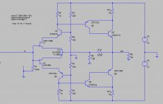
Below you can see the current model and chosen transistors. I chose the Zetex because they have really low noise, I read.
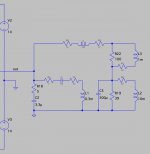
As power supply, I intend to use a Cap Mx, looks extremely nice in LTSpice, with about 1-2mV ripple.
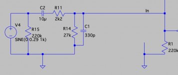
BTW, @triode_al, what is the load circuit you are using in the LTSpice model in https://www.diyaudio.com/community/threads/hiraga-le-monstre.5462/post-7075241? A cross-over?
Any comments on chosen components or else are highly appreciated.
Thanks,
Mo
I am planning to build a Le Monstre shortly. Of course I will not be able to get hold of the original FETs, so I will be using matched pairs with about 7ma Idss.
To understand what I need to change to make that work at least similar to the original, I modelled the HLM in LTSpice. Looks like the only thing needing to be addressed is the DC pot? The value below is what works well for 4R load. For 8R load, a higher value (330R or so) worked better.
For 4R load, I am getting 12W RMS with 0.3% THD. 1W RMS with 0.04% THD. Does this sound reasonable?
Below you can see the current model and chosen transistors. I chose the Zetex because they have really low noise, I read.
As power supply, I intend to use a Cap Mx, looks extremely nice in LTSpice, with about 1-2mV ripple.
BTW, @triode_al, what is the load circuit you are using in the LTSpice model in https://www.diyaudio.com/community/threads/hiraga-le-monstre.5462/post-7075241? A cross-over?
Any comments on chosen components or else are highly appreciated.
Thanks,
Mo
Attachments
Hi Mo, I used a traditional looking tube amplifier. But it was not: symetrical; 6J6 entrance, E90CC output. And +/- 150V.
In your implementation: please add a source resistor in the input, some hundred ohms.
As power supply, I recently like the SMPS packs, they are handsome and come 'ripple free'. [In my current amplifier, a Pass V-Fet, my output noise is . . . 0,1 mV]
There are complete filter packs to reduce the last switching noise. [For +/- use, you have to turn around the electrolytics of course yourself]
Hi, thanks for your comments.
Mo
I was referring to the circuit in the attachment. This is from your spice file. Not sure how your comment about a tube amp relates to that 🤔.I used a traditional looking tube amplifier. But it was not: symetrical; 6J6 entrance, E90CC output. And +/- 150V.
Yes, I will most likely even be using capacitor coupling with the attached circuit, just to be sure I can connect any preamp.In your implementation: please add a source resistor in the input, some hundred ohms.
I read this a couple times in different threads now where people used SMPS, but I somehow dislike this in an audio amp, maybe later 😀.As power supply, I recently like the SMPS packs, they are handsome and come 'ripple free'. [In my current amplifier, a Pass V-Fet, my output noise is . . . 0,1 mV]
There are complete filter packs to reduce the last switching noise. [For +/- use, you have to turn around the electrolytics of course yourself]
Mo
Attachments
HiHi,
I am planning to build a Le Monstre shortly. Of course I will not be able to get hold of the original FETs, so I will be using matched pairs with about 7ma Idss.
Any comments on chosen components or else are highly appreciated.
Thanks,
Mo
Please use the original schematic with your JFet's but replace the 1K resistors with 470R to 500R type. On the positive side you can use a 500R (1K set up 500R) Multi turn trimmer to set up the DC on the speakers terminal. I built mu that way many years a go and it worked fine.
Hi
Please use the original schematic with your JFet's but replace the 1K resistors with 470R to 500R type. On the positive side you can use a 500R (1K set up 500R) Multi turn trimmer to set up the DC on the speakers terminal. I built mu that way many years a go and it worked fine.
Thanks. I have seen two approaches to get the correct idle current with higher Idss FETs:
1) Lower the 1k to what you say, like 470R-560R
2) Raise the R of the pot to about 200R-250R
In spice, both seem to have a pretty similar effect. Is there a strong pref to either? If so, why?
My estimate: Both will reduce the 'amplification' in open loop. But having a higher source resistor has a stronger effect on lowering it.
albert
albert

You misunderstood me! Use everything as the original circuit is! Only replace at the negative rail voltage side the 1K with 470R at the positive side instead using resistor use a trimmer to set up the DC. Because of your different J Fet type or grade. Use a multi-turn pot as a variable resistor and adjust according to to your need.Thanks. I have seen two approaches to get the correct idle current with higher Idss FETs:
1) Lower the 1k to what you say, like 470R-560R
2) Raise the R of the pot to about 200R-250R
In spice, both seem to have a pretty similar effect. Is there a strong pref to either? If so, why?
Do not touch the original trimmer value. I will take a look at the schematics and will post it to you with the suggested values to avoid the further misunderstanding.
Here is a website with all the information you may need. http://www.qrp.gr/page/audio/monstre/monstre.htm Old schematics and a newer ( with the different value resistor) The trimmer would help to set up you DC offset and after you can replace it with solid resistor or just leave it that way.You misunderstood me! Use everything as the original circuit is! Only replace at the negative rail voltage side the 1K with 470R at the positive side instead using resistor use a trimmer to set up the DC. Because of your different J Fet type or grade. Use a multi-turn pot as a variable resistor and adjust according to to your need.
Do not touch the original trimmer value. I will take a look at the schematics and will post it to you with the suggested values to avoid the further misunderstanding.
Sorry, not sure I am following. The "new" schematic on the website has all Rs different and uses other FETs. And it still has only the DC offset pot.Here is a website with all the information you may need. http://www.qrp.gr/page/audio/monstre/monstre.htm Old schematics and a newer ( with the different value resistor) The trimmer would help to set up you DC offset and after you can replace it with solid resistor or just leave it that way.
And I think you speak about using 2 pots? What for? Finding the replacements for the 1k Rs to get the correct idle current?
According to what I see in LTSpice, I am getting a little over 1A idle current with Rs changed from 1k to 560R (needed for 4R speaker for staying in class A over the full power range). The DC pot can stay at 100R in this scenario.
Of course the 560R only work with the FET model I am using and the real FETs might differ in Idss again. So using a pot to find the correct value to replace the 1k's with sounds like a good idea.
Thanks, Mo
Yes, that is it. If you chose 1K Multi-turn pots you can set up your amp nicely after warm up with your J Fet Idds (what ever you get). You can do both 1K resistors. Set up 500R both side for start and you can increase it or decrease it based on your need. Changing the original (middle in the schematic) trimmer value it may change (alter / effect) the sound to. It is somewhat connected to the feedback, you do not want to play (mess) with that (unless if you have a working amp and do a very good listening test) A-B comparing between the two channel. This is the best way to preserve the original sound as much is possible. Listening to the amp and simulating is two different thinks. You want not just a good functioning amp you want a good sounding, reason to build one.Sorry, not sure I am following.
Of course the 560R only work with the FET model I am using and the real FETs might differ in Idss again. So using a pot to find the correct value to replace the 1k's with sounds like a good idea.
Thanks, Mo
Absolutely true, the simulation is only as good as the models of the components and I am using it only as a validation step.Yes, that is it. If you chose 1K Multi-turn pots you can set up your amp nicely after warm up with your J Fet Idds (what ever you get). You can do both 1K resistors. Set up 500R both side for start and you can increase it or decrease it based on your need. Changing the original (middle in the schematic) trimmer value it may change (alter / effect) the sound to. It is somewhat connected to the feedback, you do not want to play (mess) with that (unless if you have a working amp and do a very good listening test) A-B comparing between the two channel. This is the best way to preserve the original sound as much is possible. Listening to the amp and simulating is two different thinks. You want not just a good functioning amp you want a good sounding, reason to build one.
It is interesting to see though, how idle current, too low or too high, influences THD, e.g. And that can be seen quite nicely in spice.
I will also measure the final amp with the model and compare, and of course listen 🙂.
Thanks for the advice.
Mo
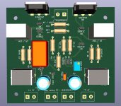
PS. current iteration of the PCB below, need to do a few optimizations, then I will send to the manufacturer.
Attachments
The monstre you could, you SHOULD build without pcb.Absolutely true, the simulation is only as good as the models of the components and I am using it only as a validation step.
It is interesting to see though, how idle current, too low or too high, influences THD, e.g. And that can be seen quite nicely in spice.
I will also measure the final amp with the model and compare, and of course listen 🙂.
Thanks for the advice.
Mo
PS. current iteration of the PCB below, need to do a few optimizations, then I will send to the manufacturer.
Q2, Q3, Q5, Q6 - I would use the same, the one, complementary-transistors-pair. I would use TO-220-types.
R2 and R4 adjustable.
NO "double-mono-psus", NO channel-separate-psus! Do use one only. (Exacter: the necessary two: "+ and -" psus for the: 2 x "+ and -" amps;-)
Great pp-design! In principle, not as good as an se, but much much much better than the vast majority of pp-end-amps - price no matter!
More than an estimate: a fact. Changing from the yellow grade to the green grade decreases the load resistor (original 1.0k), going blue grade or other types (#2189: 2SK246/2SJ103) is even more diverting from the original (2SK170/2SJ74 green grades are available still). And the yellows have the highest transconductance of the family, so other grades will have higher rs values, decreasing the open loop gain even further. If it drops to much, there will be lack of control and correction and error and distortion will increase considerable. The only way to keep to the original as close as possible is to add dc-current sources of a small value in parallel with the first stage load resistors to obtain the 'yellow' value of 1.0k again. The final values are almost always depending on the actual Idss and the stabilised setting of the Id of the fets.My estimate: Both will reduce the 'amplification' in open loop. But having a higher source resistor has a stronger effect on lowering it.
albert
Also, make sure that the Sziklai's have sufficient beta's nevertheless.
Which numbering are you referring to? The original schematic does not have any and your comments do not match the numbering on my PCB?The monstre you could, you SHOULD build without pcb.
Q2, Q3, Q5, Q6 - I would use the same, the one, complementary-transistors-pair. I would use TO-220-types.
R2 and R4 adjustable.
NO "double-mono-psus", NO channel-separate-psus! Do use one only. (Exacter: the necessary two: "+ and -" psus for the: 2 x "+ and -" amps;-)
I will definitely go with a PCB, much easier to have control over path lengths (and keeping them short to minimize crosstalk), ground etc. The only amp I would consider building without a CB would be a SE tube. Why do you think not using a PCB is an advantage?
Same question for the advice on PSU... Why would you think one is better? Here again, I will do the contrary.
Thanks for the knowledgable insight!More than an estimate: a fact. Changing from the yellow grade to the green grade decreases the load resistor (original 1.0k), going blue grade or other types (#2189: 2SK246/2SJ103) is even more diverting from the original (2SK170/2SJ74 green grades are available still). And the yellows have the highest transconductance of the family, so other grades will have higher rs values, decreasing the open loop gain even further. If it drops to much, there will be lack of control and correction and error and distortion will increase considerable. The only way to keep to the original as close as possible is to add dc-current sources of a small value in parallel with the first stage load resistors to obtain the 'yellow' value of 1.0k again. The final values are almost always depending on the actual Idss and the stabilised setting of the Id of the fets.
Also, make sure that the Sziklai's have sufficient beta's nevertheless.
Why is lowering the Rs not enough to raise the open loop gain? Do you have a pointer to a CSS which could be used?
Ah, you said it, lower transconductance. I need to read more about JFETs. They are still rather mysterious to me.Why is lowering the Rs not enough to raise the open loop gain? Do you have a pointer to a CSS which could be used?
EDIT: in the latest Toshiba datasheets I find the 2SK170A to 2SK170D (I know, all higher Idss than the Y) mentioned with same typical transconductance of 22mS. What was the typical value for transconductance for Y devices?
Last edited:
The sonic influence of changes in the circuits can be due to both: the layout and the components, materials. A clear assignment requires a comprehensive knowledge of all influencing factors.
I would prefer the simpler circuit. I would prefer the better sounding parts.
Aside: Complementary transistors sound VERY different. A complementary transistor push-pull amplifier amplifies two half-waves VERY differently sounding. This is, unfortunately, VERY audible)-;
I would prefer the simpler circuit. I would prefer the better sounding parts.
Aside: Complementary transistors sound VERY different. A complementary transistor push-pull amplifier amplifies two half-waves VERY differently sounding. This is, unfortunately, VERY audible)-;
Here is a picture out of Rod Elliots reference article (supplied) showing the relation between 'colours' and transconductance.Ah, you said it, lower transconductance. I need to read more about JFETs. They are still rather mysterious to me.
EDIT: in the latest Toshiba datasheets I find the 2SK170A to 2SK170D (I know, all higher Idss than the Y) mentioned with same typical transconductance of 22mS. What was the typical value for transconductance for Y devices?
Try to find old catalogues from Siliconix (late seventies, eighties) for an indepth understanding and application of Jfets.
Also, application notes from that era from various manufacturers are worth reading.
Most important conclusion is the considerable variation of specifications (Idss, Vgs) even within a colour or letter group.
Unless a 'production-stable' circuit is designed, one is obligated to select proper matches. Production-stable circuits yield less amplification in general (no free lunch) and often used for the high input impedance only.
The design of Hiraga is somewhat daring, and stable after the select-and-match process.
Attachments

Pics as promised! It sounds MUCH better off the batteries! A lot more quiet and better dynamics. I wired 2 power switches, one for AC power, one for DC power or both to charge. Complete with "breathing" power LED's! 😈


- Home
- Amplifiers
- Solid State
- Hiraga "Le Monstre"