No, i don't get it. I have TO3 transistors, and a huge heatsink with holes for TO3 transistors on it. This PCB is perfect, because it allows me to directly solder the transistors pins to the PCB. Isn't this the correct way? I don't want to try other transistors, i want to stick with these ones, because i know they're good. They're original SanKen ones, not cheap chinese replicas.
We have a communication problem 😀. You could reread the posts and try to understand. Otherwise let's leave it like that.
Your TO3 board is nice sir, don't misunderstand please. However we never use the word "perfect" as nothing is perfect.
Your TO3 board is nice sir, don't misunderstand please. However we never use the word "perfect" as nothing is perfect.
I think i'm going to stick with this design. I will also redesign the power supply, so that i can solder the TO247 and TO220 devices directly onto the PCB.
I didn't add the RC filter because i won't use a preamp with this. I'll build this to drive the amp: DAC with WM8740. I have a USB I2S converter at home, which is capable of producing 192kHz/24Bit audio, and the volume control will be digital.
I didn't add the RC filter because i won't use a preamp with this. I'll build this to drive the amp: DAC with WM8740. I have a USB I2S converter at home, which is capable of producing 192kHz/24Bit audio, and the volume control will be digital.
Without volume control an RC filter would be advisable. In Hiragas time cell phones and smart phones did not exist 🙂 Please note that a muting circuit is mandatory when connecting a DAC directly to an "open" power amp. Otherwise power on sequence possibly is a hazardous affair. Best case is plooiing woofers at power on/off but more often it are very annoying loud bangs that love to destroy woofers. So essentially I would encourage speaker protection too by means of uPC1237 and a silver contact relay. You will thank me for this tip when something goes wrong although everyone seems to need to experience severe damage before acknowledging the need for DC protection.
Last edited:
I will think about the construction, but i think they should be separate devices. I think the DAC includes filters, but if you say so... Can you give me the values?
1 kOhm and 680 pF is what I generally used. You might switch devices that feed the amp. Any DAC or preamp that you will use on a power amp without volume control needs a muting circuit at power on (and fast off or fast output to GND at power down). With regards to muting circuits in line devices: shorting outputs to GND has a preference as the relay contacts then won't have any negative impact on signals.
Last edited:
Dear jean-paul and fellow DIYers!
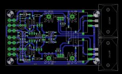
I redesigned the power supply board, and i just wanted to share it with you. I hope you will like this design!


I redesigned the power supply board, and i just wanted to share it with you. I hope you will like this design!

Of course, i would be happy to. This capacitance multiplier circuit is a slightly modified version of Rodd Elliott's.
You can find the EAGLE PCB files here: Dropbox - Hiraga Le Monstre 8W
You can find the EAGLE PCB files here: Dropbox - Hiraga Le Monstre 8W
hello,Dear jean-paul and fellow DIYers!
I redesigned the power supply board, and i just wanted to share it with you. I hope you will like this design!
nice to see a fellow eagle user...
just 1 or 2 design tips.
1. place mounting holes appropriately
2. see if you could get an exact package dimensions for all the capacitors (4700 and 1000uf/35V). that way you could save some space and place traces accordingly.
3. use faston connectors for connecting wires to pcb
reg
Prasi
Hi!
I'm going to use Nichicon FG and FW capacitors in the power supply, and i measured the dimensions of the capacitors. I've uploaded the PCB because i think that everyone should customize it for their own taste. 🙂
I'm going to use Nichicon FG and FW capacitors in the power supply, and i measured the dimensions of the capacitors. I've uploaded the PCB because i think that everyone should customize it for their own taste. 🙂
Last edited:
Thanks A LOT, this will come in handy, once I get to this project. 😀
Of course, i would be happy to. This capacitance multiplier circuit is a slightly modified version of Rodd Elliott's.
You can find the EAGLE PCB files here: https://www.dropbox.com/sh/mwfrjr8xz2u3ajd/AABW6_vVQvJDQWRQ8vDj-g5Ja?dl=0
You're very welcome. Please note, that the power transistors are placed according to my heatsink, and they're off the 0.0125inch grid.
I cant verify your PCB but i would like to give you some tips regarding this Amplifier.
If you are making your own Board, I would advice you to make the layout long as shown in below Pic. The Size of PCB is 200 x 60 mm.
This 30 Watt Amp really needs a Massive Heat Sink. I have made this Amp. I took 2 Pieces of Heat Sinks (200 x 120 (h) x 80 mm Fins height) attached them together. Mounted Each transistor on Single Heat sink. Have a look on below Image to get an Idea.
This type of Mounting will also give you enough room to place your Transformers as well as the Power Supply.
Regards,
Sadik Bhatkar
If you are making your own Board, I would advice you to make the layout long as shown in below Pic. The Size of PCB is 200 x 60 mm.
An externally hosted image should be here but it was not working when we last tested it.
This 30 Watt Amp really needs a Massive Heat Sink. I have made this Amp. I took 2 Pieces of Heat Sinks (200 x 120 (h) x 80 mm Fins height) attached them together. Mounted Each transistor on Single Heat sink. Have a look on below Image to get an Idea.
An externally hosted image should be here but it was not working when we last tested it.
An externally hosted image should be here but it was not working when we last tested it.
An externally hosted image should be here but it was not working when we last tested it.
This type of Mounting will also give you enough room to place your Transformers as well as the Power Supply.
Regards,
Sadik Bhatkar
Thank you Sadik I really appreciate your advice,but I will stay on my pcb design, however I tried my pcb and I had problems, there why I asked for pcb confirmation. My pcb can't work and output transistor on my pcb were not heating at all. I looked several times and I didn't find any mistakes. I used 400VA transformer and at power supply output I had 25.6 V (that's is supply from my Aleph 3 amplifier) but I suppose that 1,6v bigger voltage can not be a problem.
Thank you in advance,
Igor
Thank you in advance,
Igor
I did had a look on the PCB, by referring the schematic from this link Jean Hiraga's Super Class-A Amplifier i did not found any problem in your PCB layout, So i think the PCB is ok. (Please note I am not a professional Guy so i cant say weather the output transistors which you have used are compitible replacements for 2SC5200 & 2SA1943, However the pin layouts for both the Transistors are same) Now you need to check if there is a dry solder or may be some pads are shorted with tracks. In the image provided by you it looks like the pad of 0.33ohm / 5W resistor is shorted with the emitter track of output transistor.
Secondly check the voltage across those 0.33 Ohm resistors. It should be around 380 to 400 millivolts. If the measured voltage is very low then you have to change the 47K/1W resistor to set the Bias.
Couple of more question i would like to ask you.
After powering on did you checked the DC offset in Speaker output? Did u tried to connect the speakers and play a song?
Regards,
Sadik
- Home
- Amplifiers
- Solid State
- Hiraga "Le Monstre"