Here Guys the Le Monstre 8W paper about the PS :
Amplificateur 8 W "Le Monstre". L'alimentation (J.Hiraga)
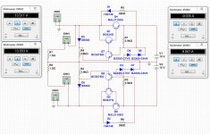
fig 14 : This was the simpliest version (without the battery which need a lot of Farads) : 0.68 F-> Resistor (4 ohms) -> 2 x 0.68 F : per rail with 160 VA and 14V ! (rectifier diodes must be 8A mini)
Here is a further review where Hiraga talk about a new model Siemens just launched (The Sikorel capacitor in 100 000 uF/25 V 🙂 with a low ESR) :
On en parle n°31, retour sur le 8W
Amplificateur 8 W "Le Monstre". L'alimentation (J.Hiraga)
fig 14 : This was the simpliest version (without the battery which need a lot of Farads) : 0.68 F-> Resistor (4 ohms) -> 2 x 0.68 F : per rail with 160 VA and 14V ! (rectifier diodes must be 8A mini)
Here is a further review where Hiraga talk about a new model Siemens just launched (The Sikorel capacitor in 100 000 uF/25 V 🙂 with a low ESR) :
On en parle n°31, retour sur le 8W
Here Guys the Le Monstre 8W paper about the PS :
Amplificateur 8 W "Le Monstre". L'alimentation (J.Hiraga)
fig 14 : This was the simpliest version (without the battery which need a lot of Farads) : 0.68 F-> Resistor (4 ohms) -> 2 x 0.68 F : per rail with 160 VA and 14V ! (rectifier diodes must be 8A mini)
Here is a further review where Hiraga talk about a new model Siemens just launched (The Sikorel capacitor in 100 000 uF/25 V 🙂 with a low ESR) :
On en parle n°31, retour sur le 8W
And if use batteries in buffer, how much F need? 🙂
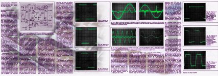
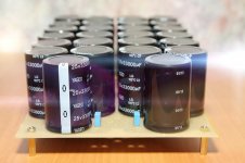
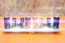
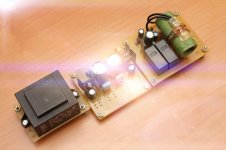
Yes in the most complex design, but you may use it without in a home environment : auto leads battery can have gaz emissions (even the so called "proof" one) : health is important ! The values are on the fig 14 for the bodybuilded one and on the pictures below (no french needed!)
But the most difficulty I see is the parts are choosed to copy a particular tube and are matched between each others... for a precise H2/H3 equilibrium.
The most F the best with a lead battery (I used to have a cd players with 1 F made from batery cells for PC for the 5V needed on a TDA1545A ! and more with // + serie for the analog output ! the transcient is not a problem : you putt a low esr cap near the load ! : it was the old method if you didn't want the fast transcient regulated supply...which has different qualities !)
Last edited:
Degazage uniquement lors de la charge!
The capacitors or reservoirs have a typical function not deeply explained by Mr. Hiraga.
Another point it is not done with only connect them on the batteries.
I'm wondering that nobody will go that way!
Jean-Paul
The capacitors or reservoirs have a typical function not deeply explained by Mr. Hiraga.
Another point it is not done with only connect them on the batteries.
I'm wondering that nobody will go that way!
Jean-Paul
You mean batteries & huges caps Versus régulation ?
Unluckily in french, there is an interresting thinking from Hiraga in the PS paper linked above for the poors & cons with smps supply vs passives... I don t undetstand it as too Much tecnich for my basic tech knowledge....
Unluckily in french, there is an interresting thinking from Hiraga in the PS paper linked above for the poors & cons with smps supply vs passives... I don t undetstand it as too Much tecnich for my basic tech knowledge....
You mean batteries & huges caps Versus régulation ?
Unluckily in french, there is an interresting thinking from Hiraga in the PS paper linked above for the poors & cons with smps supply vs passives... I don t undetstand it as too Much tecnich for my basic tech knowledge....
Ha-ha, Hi. 🙂
Not "versus".😉
Hello,
This thread is close to death but i will try to '' capture '' the thoughts in one or two lines.
The regulation seems to offer some advantages but a big problem is the high frequency noises that are kind of generated by this kind of supply which end up in the amplifier and are '' distributed '' all over other gear connected to your powerline.
Of course the usual diy member want to make it more complicated, throwing in loads of active parts. Most of them did never hear the kind of high effiency gear used by the French in combination with low power amps.
Greetings, Eduard
Hello,
This thread is close to death but i will try to '' capture '' the thoughts in one or two lines.
The regulation seems to offer some advantages but a big problem is the high frequency noises that are kind of generated by this kind of supply which end up in the amplifier and are '' distributed '' all over other gear connected to your powerline.
Of course the usual diy member want to make it more complicated, throwing in loads of active parts. Most of them did never hear the kind of high effiency gear used by the French in combination with low power amps.
Greetings, Eduard
Discrete compensation stabilizator, only discrete.., without "integrated elements".🙂
Discrete compensation stabilizator, only discrete.., without "integrated elements".🙂
Hello,
These 3 words do sound like a google translate result. In my '' diy career '' the best results so far always had a mix of the folowing elements:
Tube rectifiers whenever possible, r core or EI core instead of toriodal ones, use of static screen on transformers, using bigger transformers, choke input, LC filtering instead of RC, bigger chokes and smaller caps, double coil chokes like Lundahl, no series but only shunt regulation. Of course with tube amplication power suplly is easier because of low current.
With higher current Class A like Hiraga chokes can be used.
Did only try battery supply with class D works well. OOh did try battery with Hiraga mc prepre.
Start using chokes! so cheap they last a life time.
Greetings, Eduard
Hi. 🙂
Discrete compensation stabilizator, as example. (not final version yet)🙂😀
Attachments
Hi. 🙂
Discrete compensation stabilizator, as example. (not final version yet)🙂😀
Hello,
I cannot judge if it will work. Maybe it does but it will sound bad? Better persuade sonebody who has an Hiraga or similar amp to build this circuit and see if it does give an improvement.
Greetings, Eduard
Hello,
I cannot judge if it will work. Maybe it does but it will sound bad? Better persuade sonebody who has an Hiraga or similar amp to build this circuit and see if it does give an improvement.
Greetings, Eduard
When I'll make it - then I'll know.🙂
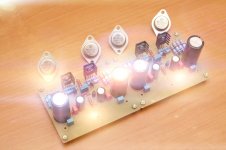
Jean Hiraga's Class A 20W in building process...🙂🙂🙂😱
Attachments
-
 Hir20W ART 001.jpg483.8 KB · Views: 738
 -
 Hir20W_a01.jpg818.4 KB · Views: 698
 -
 Hir20W_a07.jpg671.6 KB · Views: 668
 -
 Hir20W_a03.jpg174.1 KB · Views: 602
 -
 Hir20W_a02.jpg150.1 KB · Views: 629
 -
 Hir20W_a04.jpg131.2 KB · Views: 365
 -
 Hir20W_a05.jpg122.2 KB · Views: 296
 -
 Hir20W_a06.jpg176.2 KB · Views: 290
 -
 Hir20W_a08.jpg769.1 KB · Views: 291
Nice !
Are they said (the output transistors) to be a good swap in relation to the originals of the BOM ?
Do the need to be sorted ?
Are they said (the output transistors) to be a good swap in relation to the originals of the BOM ?
Do the need to be sorted ?
Nice !
Are they said (the output transistors) to be a good swap in relation to the originals of the BOM ?
Do the need to be sorted ?
Small transistors must be sorted very hard (and must have linear HFE on 0,8-4mA), output better to sort (at 1-2A bias).
One with original NEC transistors and teflon boards and holco resistors on sale :
Hiraga 20W Class A Power AMP Board KIT | eBay
Hiraga 20W Class A Power AMP Board KIT | eBay
- Home
- Amplifiers
- Solid State
- Hiraga 20W class A