TRy ferrite beads in mosfet gates..they work wonders esp at 6MHz. The reason why I am fussy about reverse transients is that I work in motive power electronics when a single lightning flash to the overhead catenary is still the most effective spike in blowing up tram and train inverter electronics especially when 3 phase is created from a single and a spike crashes the lot. This makes EMC a nice little earner and is mighty expensive for businesses. Poor cramped multilayer boards with few earthing vias is nearly always asking for trouble.
I use a 10-47uF on the output. This adds an HF cutoff pole and reduces noise.
ANother bit of investigation is to listen to the noise on the output. This bit isn't for experimenters....a good 0.1uF HV cap into an HP 311 audio analyser input terminated with a 600R resistor and output monitor into an amp/loudspeaker will tell one by the noise if pSU is about to oscillate. This takes skill and this carries a voltage risk. You know what you are doing in order to do it.
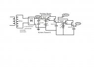
One of the drawbacks of designing for transients, it can lower the dv/dt circuit response but is the most secure and reliable. Notice, where there is a cap in the error or pole correction, there is a resistor in series with it.......to many this goes against theory but the problems can be worked.
Enclosed is a simplest version of a regulator I used for a 7+7W amp with considerably high o/p capacitance.
richy
richy
I use a 10-47uF on the output. This adds an HF cutoff pole and reduces noise.
ANother bit of investigation is to listen to the noise on the output.
This bit isn't for experimenters....a good 0.1uF HV cap into an HP 311 audio analyser input terminated with a 600R resistor and output monitor into an amp/loudspeaker will tell one by the noise if pSU is about to oscillate. This takes skill and this carries a voltage risk. You know what you are doing in order to do it.One of the drawbacks of designing for transients, it can lower the dv/dt circuit response but is the most secure and reliable. Notice, where there is a cap in the error or pole correction, there is a resistor in series with it.......to many this goes against theory but the problems can be worked.
Enclosed is a simplest version of a regulator I used for a 7+7W amp with considerably high o/p capacitance.
richy
richy
Attachments

Richy,
I really appreciate your inputs. It's great to get input from someone who designs circuits that can tolerate lightning for a living... It gives you a different perspective - in your case attention to high dV/dt spikes. Just like my work on circuits on silicon dice has made me keenly aware of device characteristics vs voltage, temperature, current, etc.
Thanks!
~Tom
Richy,
I'm guessing it's the 10R+15nF that provide the soft return path for the high dV/dt pulses?
~Tom
I'm guessing it's the 10R+15nF that provide the soft return path for the high dV/dt pulses?
~Tom
Yup, these aren't critical values......except carbon resistor used as spike dump. Carbon films are ok and be sensibly rated. The mistake many make is using m/o/film types which are useless for handling transients. The same holds true for the current sensing resistor often used in fixed bias o/p stage cathodes to ground, where a 1% wirewound is the best choice here.
i have been working on a Maida architecture HV regulator for a single ended amp using a KT88 and have been experiencing the same problems your were having. i came across this thread while researching for ideas to solve the problems. Can you tell be what your operating experience has been over the last few months since you completed your design on June 4? has it been reliable and continues to meet your expectations? your final design appears to be clean and elegant.
Well.... So far so good. Before I published the design, I actually torture tested it quite a bit using resistors, light bulbs (a tough load actually!), and of course a real amplifier. I have yet to make it fail. Rich Walters have provided a lot of useful feedback on the design, and I've summarized those points on my website (www.neurochrome.com/audio) which is also where you can buy the PCBs. I've sold a good handful of boards at this point and haven't received any requests for support or concerns about the design at this point.
I'm still building my amplifier, actually. Currently I'm working on filament supplies and test equipment to test said supplies. So I can't comment on the long-term reliability of the circuit. But provided with a good heat sink, I see no reason why it would fail.
Once I get some more test equipment built, I intend to post more data on this regulator. Specifically, I'd like to measure its output impedance. I bet it's quite low.
Thanks,
~Tom
Last edited:
I've been using BC components PRO-2 metal films for the majority of valve applications - they have a pretty damn good pulsed power performance, and one would be pretty hard pressed to not find them suitable for snubber applications if the layout could not be improved by a smaller part.
Constraining the gate voltage from drain dV/dt is a worthwhile focus, and may require a look at source resistor and zener layout, and possibly some more Cgs, and a lower zener voltage.
Constraining the gate voltage from drain dV/dt is a worthwhile focus, and may require a look at source resistor and zener layout, and possibly some more Cgs, and a lower zener voltage.
I agree about using lightbulbs for a dummy load. start off as an almost dead short until they heat up. nice start of a web site. a couple of questions:
Is the regulator board mounted some circuit distance from the 5AR4 and its capacitor filter and that is why you have included C1A/C1B on the board? Or is there another reason...
Are you going to have one regulator board for both left and right channel amplifiers or are you planning on two regulators, one for each channel? i believe i recall that you are building this regulator for a load of 300mA which would appear that you are going to have one regulator for the two channels.
C1A/C1B is local decoupling. I always put a little cap on the supply inputs on my boards. Having a low-impedance supply saves so much trouble with RF oscillations and other nastiness. I'm actually using solid state rectification, but a tube rectifier such as the 5AR4 could be used as well. The rectifier is mounted a bit away from the regulator - that's just how it worked out in the chassis. Hence the requirement for local decoupling.
My original thought was to have one regulator per channel. But due to chassis limitations and the fact that this regulator can easily provide a few hundred mA, I have chosen to go with one regulator for two channels. The total current draw will be 180 mA. For a SET in Loftin-White configuration, I think this should be fine.
~Tom
looking through your parts list of June 4. R1 and R2 are listed as a 0805 package, but the digikey P/N is an axial lead. which is it? after a quick check on parts availability, i will purchase a few of your boards.
looking through your parts list of June 4. R1 and R2 are listed as a 0805 package, but the digikey P/N is an axial lead. which is it? after a quick check on parts availability, i will purchase a few of your boards.
DOH! Well... Thanks for the proof reading 🙂
R1, R2 are 0805 SMD types. The Digikey P/N in the BOM is not correct.
Thanks,
~Tom
The correct part numbers are:
R1 : 82 kOhm : Digikey P/N 311-82KARCT-ND
R2 : 1 Mohm : Digikey P/N 311-1.0MARCT-ND
They're standard, run of the mill 5 % thick film 0805 resistors. 1.7 cents each.
~Tom
R1 : 82 kOhm : Digikey P/N 311-82KARCT-ND
R2 : 1 Mohm : Digikey P/N 311-1.0MARCT-ND
They're standard, run of the mill 5 % thick film 0805 resistors. 1.7 cents each.
~Tom
i have been working through some of the details of using this regulator for my amp and am trying to figure out the best place to add the standby control so that the high voltage can be turned off or turned low at initial energizing and when desired during operation.
the 'Jones' method is to add a 'zero crossing' relay (triac) on the primary. the Amateur Radio method is to add a relay/switch on the CT of the transformer HV winding, or another method would be to add a switch/relay into the regulator.
have you given any thought to this? one thought i had was to add another resistor or two to the voltage sensing resistors controlled via a relay/circuit so that the regulated voltage could be dropped when desired. one issue to be considered for the relay/circuit is that the regulator is at an elevated voltage from neutral and that any connection to the real world would have to have suitable voltage isolation.
First off, I would use a relay or TRIAC of some sort rather than having a high-voltage switch accessible to the user.
I would probably avoid adding switches to the regulator itself. One could entertain the idea of shorting out the lower resistor in the feedback network (R8). During start-up this would work fine. In this condition, the output voltage is 2.5 V. But I bet that the chances of letting the magic smoke out of the parts is pretty high if you short out R8 at full output voltage.
Many people report issues with lifting the center tap of the mains transformer. You get some fairly nasty ringing in the transformer secondary when you do that. This tends to kill rectifiers as far as I understand.
So I'd probably suggest that you add a relay on the input side of the regulator and call it good.
But unless you absolutely want the ability to turn off the HV during operation, you don't really need any relay. The start-up time of the regulator is about a minute, so the filaments of your tubes are nice and hot by the time B+ is applied. I'm not getting any turn on/off thumps in my SET amp powered by this regulator.
~Tom
thx. it appears i should leave the regulator circuit alone and go with the relay turning off the HV. regarding lifting the center tap of the mains transformer; i saw this ringing on my old tube SW radio a while ago while playing around with it, didnt know what was causing it, but it wasnt a concern at that time. now i know why.
will order a few circuit boards and will build up a regulator and let you know my experiences if you are interested.
will order a few circuit boards and will build up a regulator and let you know my experiences if you are interested.
Saw your order. Thanks a bunch!! The boards will ship tomorrow morning. International Priority takes 6~10 business days and I'd expect the transit time to Canada to be on the shorter end of the range.
Please do let me know of your experiences. I'm always looking for feedback and ways to improve.
Thanks,
~Tom
Please do let me know of your experiences. I'm always looking for feedback and ways to improve.
Thanks,
~Tom
As an aside, a MOV across secondary HT winding(s) should alleviate overvoltage transients from CT disconnection under load. I typically put a small MOV on the primary, especially for older transformers, for the same reason.
Ciao, Tim
Ciao, Tim
I've updated the BOM to include the correct part numbers as listed in Post #193 above.
Neurochrome.com : : Audio – High-Voltage Regulator
~Tom
Neurochrome.com : : Audio – High-Voltage Regulator
~Tom
- Status
- Not open for further replies.
- Home
- Amplifiers
- Power Supplies
- High Voltage Regulators (Maida or zener)