A zener + source/emitter follower like you have is fine for many purposes. However, its output impedance is a bit on the high side (1/gm for MOS, re for BJT) -- in many cases 10-ish ohm or so. In addition, the output voltage isn't very tightly controlled. It's basically limited by the precision of the zeners (typ. +/- 5 %) and the Vbe or Vgs. So in addition to a DC inaccuracy, there's also a temperature component.
In many cases, the zener regulator is fine. But as you can see in some of the earlier posts, I had issues with SOA failures of the pass device during start-up. A zener regulator does nothing to address this. In fact, I did try a zener regulator and fried the 12 A pass device on turn-on. The high voltage regulator I ended up with has a nice smooth start-up, hence, no issues with SOA failures when starting up into a capacitive load. Mind you that I'm running 600 V in and 475 V regulated out... So for my application, I ended up needing a more complex design.
One of these days I'll get around to measuring the output impedance of that regulator. It should be pretty low... Stay tuned.
~Tom
How many volts between Vin and Vout do this reg need to operate well?
It might be that I could find the answer in the thread but I tried reading without results. Appologies if it is just that I did not search well enough.
It might be that I could find the answer in the thread but I tried reading without results. Appologies if it is just that I did not search well enough.
I'm not sure I touched on that in the thread. It's a very relevant question.
I seem to recall the drop-out on the prototype being on the order of 15 V. I would recommend designing for at least 25 V drop-out to have a bit of margin.
So, under worst-case conditions (lowest input voltage) the input voltage should be 25 V higher than the output voltage.
~Tom
I seem to recall the drop-out on the prototype being on the order of 15 V. I would recommend designing for at least 25 V drop-out to have a bit of margin.
So, under worst-case conditions (lowest input voltage) the input voltage should be 25 V higher than the output voltage.
~Tom
Last edited:
regarding the high voltage regulator offered by andresfont, i too wonder about the potential failure where the device operates outside its safe limits as i have seen failures on the main transistor as well. the transistor specified has a 1500V rating for a circuit at 565 volts; therefore the successful operation appears to have been achieved by oversizing the transistor rating.
i wonder if a capacitor added in parallel with the zeners would moderate the response at energization slowing the regulator based on the capacitor charging rate suficiently to address the SOA concern as this appears to be suggested in similar designs i have seen?
i wonder if a capacitor added in parallel with the zeners would moderate the response at energization slowing the regulator based on the capacitor charging rate suficiently to address the SOA concern as this appears to be suggested in similar designs i have seen?
I'm not sure I touched on that in the thread. It's a very relevant question.
I seem to recall the drop-out on the prototype being on the order of 15 V. I would recommend designing for at least 25 V drop-out to have a bit of margin.
So, under worst-case conditions (lowest input voltage) the input voltage should be 25 V higher than the output voltage.
~Tom
Thnx Tom.
I have a reg from Gary Pimms website up and running, but that one needs something like 70V margin. The lower margin saves a few, but often valuable voltages from the supply.
regarding the high voltage regulator offered by andresfont, i too wonder about the potential failure where the device operates outside its safe limits as i have seen failures on the main transistor as well. the transistor specified has a 1500V rating for a circuit at 565 volts; therefore the successful operation appears to have been achieved by oversizing the transistor rating.
The pass transistor I use is rated at 950 V, 10 A. But as with any other transistor it cannot handle 950 V and 10 A at the same time. That's due to the thermal SOA limit.
In my case, I need a regulator that can start up into a short circuit (or almost). The supply input to my amp sees a 47 uF cap in series with a 500-ish ohm resistor. So the current at start-up is about 1 A. At that point, there's over 600 V across the regulator. The pass device cannot handle 600 W of dissipation. This is why even this large device fries if it isn't fitted with a soft start or current limiter.
Hence, I designed the regulator to have a rather slow turn-on (see plot in Post #156). It takes about 60 seconds for the output to reach the full output voltage, so the output current - even into my "short circuit" capacitive load never blows the device.
In addition, I fitted it with a current limiter. - Although, in my circuit, the current limiter never trips.
i wonder if a capacitor added in parallel with the zeners would moderate the response at energization slowing the regulator based on the capacitor charging rate suficiently to address the SOA concern as this appears to be suggested in similar designs i have seen?
It might. But keep in mind that the current in the zeners is typically 5~10 mA supplied through a resistor. During start-up the capacitor has to collect this charge to prevent the voltage from rising too fast. So if you want a reasonable start-up time (at least a few 10's of seconds) you'll probably find that you need a very large capacitor. You can go with a CCS for the zener stack and maybe reduce the size of the cap as its charging current would be constant. But now you're approaching the cost and complexity of a regulator...
I have a reg from Gary Pimms website up and running, but that one needs something like 70V margin. The lower margin saves a few, but often valuable voltages from the supply.
Yep. That's why I designed it that way. I think the theoretical limit is (Vin - Vout) = 10 V as that's the point where D1 starts conducting. In the lab I recall it starting to get cranky at 12~15 V DC -- but that does not include ripple. I bet the ripple pushed it below 10 V drop-out. I'll stick with my general recommendation of 25 V drop-out (worst case). But you might be able to squeeze a few more volts out of it.
~Tom
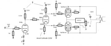
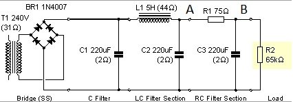
Hi guys. Sorry to drop in like this but I built a maida regulator exactly as in Morgan Jones Valve Amplifiers and have a few questions. I managed to get it to 320.0-320.1V stable. I use it to feed the final stage with 2xEL84 PP topology. Got ccs in cathodes set at 96mA (with lm317 as well). I intend to use another one for the driving/pi stages. Both need 320V as well and wondered if there are any problems with adding another one. First stages draw about 28mA together (I use 6n6p for both). My questions are about the psu. At the begining of the project I used a RC network, lately I added a choke to filter a bit and get some voltage back from the resistor it replaced. I get the voltage for the el84 regulator after the choke, and currently the voltage for first stages is taken after the next resistor in PSU. I saw some discussion on maida regulator topic and I am curious if I'll use regulators for all the stages, is there any point in keeping the choke? Should I just put the connection of the regulators at the first cap after the rectifier or it's better to keep the choke for additional filtering? I plan to use separate regulators for final stage on each channel and one on both driving/pi stages on each channel. That would be 4 regulators total. I added my circuit and current PSU. From the A point to final stage is the regulator and B (about 325-330V) goes to the first stages at the moment. R2 is the bleeding resistor.
Attachments
The reg will eat up the ripple pretty efficiently as long as the trough of the ripple waveform is still well above the dropout voltage. That said, if your grounding is good, the extra filtering won't hurt and may even help a bit- ripple rejection isn't infinite. And the extra drop beforehand reduces the amount the pass transistor has to dissipate.
I haven't simmed your filter, but you might want to check it for stability in the face of a stepped CCS load. The first cap in the filter could possibly be reduced in size, which will lower ripple current.
I haven't simmed your filter, but you might want to check it for stability in the face of a stepped CCS load. The first cap in the filter could possibly be reduced in size, which will lower ripple current.
The reg will eat up the ripple pretty efficiently as long as the trough of the ripple waveform is still well above the dropout voltage. That said, if your grounding is good, the extra filtering won't hurt and may even help a bit- ripple rejection isn't infinite. And the extra drop beforehand reduces the amount the pass transistor has to dissipate.
I haven't simmed your filter, but you might want to check it for stability in the face of a stepped CCS load. The first cap in the filter could possibly be reduced in size, which will lower ripple current.
To a 47-100uF? Also I see that you are recommending a 47uF cap in series with the final resistor in the regulator. I use a 2R7 one with 0.47uF in series at the moment.
What drawing software did you use for the pcb layout on your RLD regulator? I'm having some trouble squeezing everything nicely and tight. Does anyone have a link to a Morgan Jones HT regulator PCB? Did one by marker but it's huge 🙂 I want to try the laser copier method.
My board was done by Pinkmouse. I think he used Eagle. "Tight" is good for low resistance/inductance, but thermal management needs to be considered.
There are different philosophies about output caps and regulator transient response. I believe that a slow response is preferable- after all, an ideally regulated supply has a transient response of near infinity.
There are different philosophies about output caps and regulator transient response. I believe that a slow response is preferable- after all, an ideally regulated supply has a transient response of near infinity.
Do you recommend to change the lm317 ccs in the cathodes of el84 with a MOSFET cascode like the one in your phono preamp? Cathodes will be at arround 10V with about 100mA current drawn.
100 mA is a bit much for the simple DN2540 cascode. You do understand that using a CCS there will limit you to class A with very questionable overload recovery?
100 mA is a bit much for the simple DN2540 cascode. You do understand that using a CCS there will limit you to class A with very questionable overload recovery?
I tried your approach with led array and couldn't get more than 50mA on both cathodes. Don't know why, I built your RLD regulator as well in the setup. So I changed to CCS to get the required current for el84. My array was made from 6x7 red leds, and each had about 1.9V drop. That put it at 11.4V. Didn't put the 4R7 paralleled resistors in there, only the tail 1R one to measure the current. Max voltage was 280-290V from the regulator with pot at max. I really liked the led array and would have loved to keep it there.
There's a lot of variation in output tubes- if the idle current is too low, remove one LED from each string. With some tubes, I had to remove two from each string.
There's a lot of variation in output tubes- if the idle current is too low, remove one LED from each string. With some tubes, I had to remove two from each string.
Ok, then. I will try it once again with less leds. I think the idle current varies between the EL84 RFT's and 6p14p-ev's. I noticed some changes with that swap. But this way I'll be limited to pentode mode. Is there any way to adapt for triode mode operation with leds in cathode? I also tried a global feedback with a 1R resistor following the 2 IR leds from driver stage, and I connected the resistor from opt secondary there between the resistor and led. Is this a good approach to global feedback with leds in cathode of driving stage? Pure pentode doesn't quite cut it for me. But I have bad opt's so I see this when I get my replacement C-core opts. Thank you and sorry to divert the subject of this topic.
Pure pentode works great if you use a feedback loop or a Schade-type connection. If not, you'll get excessive bass distortion and high source impedance.
For triode or UL, the only way you can finely adjust the idle current is with the B+, which is a tougher proposition than just changing the screen voltage.
For triode or UL, the only way you can finely adjust the idle current is with the B+, which is a tougher proposition than just changing the screen voltage.
I took out 7 leds, now I have 5x7 (7 parallel strings of 5 in series). bias at 9.5V and 72mA current.
G2 is at 304V via regulator. plates are at 306-307V.
If this is the best it can do I will settle for this if CCS is not good soundwise here.
Forgot to mention that it sounds better anyway! 🙂
G2 is at 304V via regulator. plates are at 306-307V.
If this is the best it can do I will settle for this if CCS is not good soundwise here.
Forgot to mention that it sounds better anyway! 🙂
Last edited:
9.5V for 5 LEDs seems a bit high. Usually, you get about 1.7V per LED, so five would result in 8.5V. What kind are they?
OSNR5134B OPTOSUPPLY - LED | Transfer Multisort Elektronik
exactly this one. I got 100 from a local supplier that deals with TME.
Measured they got about 1.9V drop.
Got them real cheap, 4 euros all of them.
exactly this one. I got 100 from a local supplier that deals with TME.
Measured they got about 1.9V drop.
Got them real cheap, 4 euros all of them.
- Status
- Not open for further replies.
- Home
- Amplifiers
- Power Supplies
- High Voltage Regulators (Maida or zener)