Just out of interest (although somewhat related to the thread title) has anyone tried making an HV shunt regulator out of a string of 6.2V zeners?
I.e. for 200V just strung 32 zeners on a veroboard?
Whats the noise level ?
Regards
M. Gregg
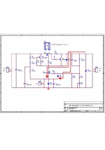
The final schematics and bill-of-materials attached. Enjoy. I have included the Digikey part numbers, but, of course, the parts can be obtained elsewhere as well.
~Tom
Tom,
Do you have a pic of a built board?
Regards
M. Gregg
Just out of interest (although somewhat related to the thread title) has anyone tried making an HV shunt regulator out of a string of 6.2V zeners?
I.e. for 200V just strung 32 zeners on a veroboard?
If you do the basic calculations on the 32x zener shunt, it will soon become clear why it is not found in any applications.
Have a look at (eg) BZX55C6V2, Vishay data sheet. You'll see:
For 5mA test current:
- Vz can be anywhere from 5.8V to 6.6V;
- The (1kHz) dynamic resistance is specified at 10 ohms.
Dynamic resistance is dependent on shunt current, but a regulator with anything like 320-ohms of output impedance is not really a regulator at all!
IF the idea really appeals to you, feed the 32 zeners with a constant current, and buffer them with a PNP emitter follower [MJE 350 is obvious choice]. But you still have to deal with some noise and accuracy problems, so you'll do better to ditch the idea and use a well-proven circuit like the SSHV.
If you do the basic calculations on the 32x zener shunt, it will soon become clear why it is not found in any applications.
Have a look at (eg) BZX55C6V2, Vishay data sheet. You'll see:
For 5mA test current:
- Vz can be anywhere from 5.8V to 6.6V;
- The (1kHz) dynamic resistance is specified at 10 ohms.
Dynamic resistance is dependent on shunt current, but a regulator with anything like 320-ohms of output impedance is not really a regulator at all!
Yeah... I looked at doing a zener stack using three 150 V zeners plus a 47 V at the "top". My goal is to get to 475 V. The plan was to feed the zeners with a CCS (IXYS IXCP10M90S) and have a potentiometer across the "top" 47 V zener. This would allow for +/-5 % adjustment. The voltage from the pot would be RC filtered and fed to a source follower driving the output voltage.
I didn't like this solution for a number of reasons. As I noted at the beginning of this thread, I had issues with the in-rush frying the pass device, hence, I need either a very slow start-up or a reliable current limiter - or both. Depending on the exact circuit topology, implementing a current limiter that's reliable and doesn't cause parts to fry is a bit tricky in case of the zener stack with source follower. A common way to implement this would be to clamp the zener voltage to GND in case of a short circuit. Works well in low-voltage circuits, but for high voltage circuits, the power dissipated in the CCS feeding the zener stack can cause trouble during current limiting. There are other issues as well.
The other thing I didn't like about the zener stack + source follower is that the output impedance is set by the drain-to-source resistance of the follower. This resistance varies with voltage, current, temperature, and probably frequency as well. This may not be an issue in most circuits, but the engineer in me kept saying "there must be a better way".
And, as Rod points out, the tolerances on the zeners are quite lax. I actually found it hard to guarantee that the zener stack could hit the target voltage without requiring excessive headroom on the input voltage.
So... That's how I landed at the floating regulator.
That said. For lower voltages and output currents, the zener stack with source follower works fine. In fact, that's what I use for the negative (-170 V) rail in my amp. Works well here. The current draw is only about 10 mA and the output impedance of the regulator can be kept in check with a good quality capacitor. The Maida regulator would work well here as well. Though, a few zeners and a MOSFET beat the Maida on complexity any day of the week. Maybe not on performance, but definitely on complexity... 🙂
~Tom
Do you have a pic of a built board?
I expect to have one by tonight. Stay tuned...
~Tom
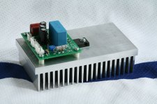
I decided to build my regulator as a module (stare at attached image).
The heatsink is a 5.375" wide, 3" tall profile from Heatsink USA. The reason for the rather large heatsink is that the input voltage is rather high - about 575 V nominal. At 200 mA output current, this results in about 20 W dissipated in the pass device. As I generally don't like having heat sinks run hotter than about 60 deg C, I went large...
After one hour at 205 mA output current, 575 V input voltage, the heatsink reaches 60 deg C with 25 C ambient measured by an IR non-contact thermometer. At this temperature, the pass device case reached 82 deg C.
With the component values on the schematic/BOM, the regulator will deliver a bit over 100 mA. To support 200+ mA, I changed R4 to 1.5 ohm.
~Tom
Attachments
Last edited:
Often stuck in situations like this, I use several sections of programmable TL431 in series which have a much lower dynamic resistance. > More components, yes but I find the performance worth the trouble.
richy
richy
Often stuck in situations like this, I use several sections of programmable TL431 in series which have a much lower dynamic resistance. > More components, yes but I find the performance worth the trouble.
Nifty! How many sections do you generally need to reach the 250~450+ Volts needed for tubes?
~Tom
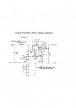
TL431 can take 37V max.....however it's only a small bit of sand.. lets be fair to the device.... I aim for 30V or lower. Brainstorming a 5 min botchup, a few 431 devices put in part of a reg design can work wonders. I added an external TVS's as protection as my electrical area is quite spiky.
This configuration works and part of my power amp designs.
As we all should know, it's virtually impossible to guarantee short circuit protection for HV SS regulators, simple fold back just to illustrate circuit current limit. Don't take s/c protection for granted !
Dissipation is another matter.
richy
Attachments
TL431 can take 37V max.....however it's only a small bit of sand.. lets be fair to the device.... I aim for 30V or lower. Brainstorming a 5 min botchup, a few 431 devices put in part of a reg design can work wonders.
I was there earlier... Except I used a 0A3 tube for the reference. I had issues with ripple rejection. The ripple was coming in via the CCS I used to power the reference and error amp. I see you have a 10 uF in your circuit to combat that. 10 uF/450 V is manageable. The worst case input voltage to my regulator is over 600 V, so I ended up with 1 uF/875 V polypro. That wasn't enough to kill the ripple feed-through, so I started playing with the floating regulator. When in doubt throw loop gain at the problem... 🙂
As we all should know, it's virtually impossible to guarantee short circuit protection for HV SS regulators, simple fold back just to illustrate circuit current limit. Don't take s/c protection for granted !
Dissipation is another matter.
Tru dat! It'll probably survive a short for a few seconds, but not long term for sure. Same for mine...
What's wrong with a Vbe multiplier + series pass transistor?
Nothing wrong with that per se. I would, however, be mindful of the temperature variation of said Vbe multiplier. I can't say off the top of my head if it'd be an issue or not. I'd have to do the math/simulation. Just something to look at.
~Tom
Ah.... thats where I found problems can start with too much gain and bode plot gets tight as a high value o/p cap is required to deal with the o/p filter ESR pole which gets sensitive je higher the gain. Many builders go wrong by underestimating the wide b/w of mosfets by using lanky tracks....see earlier pic of ferrite beads in gate/source. There are some pole issues with the circuit I provided, but it works. I find the cue for high voltage stability and circuits with a tendency to oscillate, is lowish gain to keep related gain overshoot and noise down. That also holds true for power factor circuits where the cos is 0.99 and where excess gain is never needed.
As with regulator circuits, the stability test close to dropout and overvoltage are essential with a wide range load and will test stability.
I never aim for perfect o/p voltage regulation in HV circuits as tube stuff never needs it...exception being AC ripple rejection where the CS voltage stabiliser regulator is the key. The TL431 is a perfectionist at this.
Rounding up....all of us who design and work with HV SS regulators are a bit in our own world so to speak of. Either one grasps the issues or one doesn't. It will test'ya experience...often to a big BANG.
 For any newcomers on the learning curve....take note. This is serious stuff ! not for veroboard. SOme of us over the decades have gotton rather adhock with high voltage and treat the joules rather casually. It's a practical experience curve.
richy
Does it have to be that well regulated?
There are simple ways to reduce the temp. drift of the Vbe.
There are simple ways to reduce the temp. drift of the Vbe.
Ah.... thats where I found problems can start with too much gain and bode plot gets tight as a high value o/p cap is required to deal with the o/p filter ESR pole which gets sensitive je higher the gain.
Well... Yeah. It's the usual game. Regulation is too loose, increase loop gain. Now there's stability problems. That's why I ended up with R10 and C3. The pole formed by the gate capacitance of the FET formed a pole in the low MHz range with the output impedance of the op-amp, causing, slight instability.
I never aim for perfect o/p voltage regulation in HV circuits as tube stuff never needs it...exception being AC ripple rejection where the CS voltage stabiliser regulator is the key. The TL431 is a perfectionist at this.
I don't mind if the output voltage drifts a little bit with load current or temperature. But I do want ripple rejection. That's one reason I'm using a regulator in the first place.
Had I been aware of the TL431 when I built by discrete regulator, I would probably have given it a whirl.
Rounding up....all of us who design and work with HV SS regulators are a bit in our own world so to speak of. Either one grasps the issues or one doesn't. It will test'ya experience...often to a big BANG.
Very, very true. I have built some death traps on the lab bench that I would never encourage anyone else to build. Keep hands off the high voltage. You only get one chance.
~Tom
Does it have to be that well regulated?
There are simple ways to reduce the temp. drift of the Vbe.
Oh... I didn't think about that. I normally use Vbe multipliers to get the tempco. In one case, I used one in place of a resistor when I needed a specific voltage drop. It was lower noise than the resistor. This was on silicon so the resistors were noisier (1/f noise) than discrete resistors would have been.
How well regulated does it have to be? That's a good question. The perfectionist in me wants it to be dead nuts on. But that'll never happen (it's a statistical thing and I can prove it 🙂). If it varied a few volts - say +/-1 % with temperature I probably wouldn't care much.
~Tom
Actually, there is one very practical thing I really like about this regulator. It doesn't use many power components. One pass device. One power resistor. The components are easy to find.
Another thing is that it is possible to build and test the regulator at low voltage before plugging it into the B+. Short out R8 with a piece of wire and connect ONLY the 6.3 VAC heater winding. Do NOT connect the high voltage. Power up... Measure output voltage. You should have 2.5 V on the output. If that works, leave the voltmeter connected to the output, turn the power off, wait for caps to discharge, remove the wire jumper on R8, plug in the HV and power up again (preferably slowly on a variac -- wear safety glasses in case something blows up). You should now have full regulated output voltage.
~Tom
Tom looking at your pdf schematic, I notice with no ouput cap there is a possibility for a reverse transient to spike through D1,Q4,D4 although this swamped by the 22nF and to a lesser extent C1,D3, D4 same comments as other. You probably see what I am getting at....a nasty dv/dt transient reverse spike created by an output socket connection or connection whilst on will destroy one of these components leading to another.
My survival experience with such circuits is a soft transient return path must be provided, this is where carbon resistors are excellent. Metal oxide and metal films are hopeless for transients and will go "high" but fine for reference stages.
Instability must be avoided......this causes unwanted dissipation and worse still, "birdy noises and whistles" which are easily picked up in amp stages.
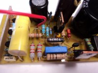
Correctly designed, the noise floor my regulator is quite low, -90dB down and ripple rejection around -80dB. With this type of design, the Line voltage variation performance to output voltage does vary a few mV but still good.
Enclosed is a pic of my regulator. note ferrite beads on mosfet and the use of a wirewound resistor in the current limit. Essential !
To constructors, note components are elevated off the board, the reason is anything stuck around components is easily seen and dust easily blown off.
richy
My survival experience with such circuits is a soft transient return path must be provided, this is where carbon resistors are excellent. Metal oxide and metal films are hopeless for transients and will go "high" but fine for reference stages.
Instability must be avoided......this causes unwanted dissipation and worse still, "birdy noises and whistles" which are easily picked up in amp stages.
Correctly designed, the noise floor my regulator is quite low, -90dB down and ripple rejection around -80dB. With this type of design, the Line voltage variation performance to output voltage does vary a few mV but still good.
Enclosed is a pic of my regulator. note ferrite beads on mosfet and the use of a wirewound resistor in the current limit. Essential !
To constructors, note components are elevated off the board, the reason is anything stuck around components is easily seen and dust easily blown off.
richy
Attachments
I notice with no ouput cap there is a possibility for a reverse transient to spike through D1,Q4,D4 although this swamped by the 22nF and to a lesser extent C1,D3, D4 same comments as other.
For a second you had me confused there.... You're referring to the older design (Rev. 2.0) not the new, floating design (3.2).
How much output cap would you recommend as a minimum to deal with such reverse spikes?
You probably see what I am getting at....a nasty dv/dt transient reverse spike created by an output socket connection or connection whilst on will destroy one of these components leading to another.
Yep. That's a really good point, actually. Thanks for bringing it up.
My survival experience with such circuits is a soft transient return path must be provided
Would you provide a schematic that shows an example?
Instability must be avoided......this causes unwanted dissipation and worse still, "birdy noises and whistles" which are easily picked up in amp stages.
With the little instability I had - actually it was more of a marginal stability except at high load current where it turned to downright instability - I was really quite surprised that the regulator would happily regulate to the right DC op point, but would hum at 6 MHz with a very low amplitude (20 mVpp as I recall). For a second I had it confused with EMI, but when I measured it to be 6.4 MHz (quite close to the UGBW of the op-amp) my suspicion of instability grew. The current incarnation of the regulator is stable. I'm not expecting any birdies.... 🙂
Correctly designed, the noise floor my regulator is quite low, -90dB down and ripple rejection around -80dB. With this type of design, the Line voltage variation performance to output voltage does vary a few mV but still good.
That's impressive.
~Tom
- Status
- Not open for further replies.
- Home
- Amplifiers
- Power Supplies
- High Voltage Regulators (Maida or zener)