When talking to an EE I would refer to a ferrite rod coil as an antenna. When talking to other people I would call it an aerial. Magnetic loops, with or without ferrite, are used to radiate so are antennas/aerials.monty78pig said:I would refer to the ferrite rod as an 'antenna'. When I think of aerials, I think of radiating elements. I would not consider a magnetic loop antenna to be an aerial.
Hmm... I suppose it's the outdoor element, as well. To be in the air, so to speak.
Most of the loop antenna's that I've seen were indoor units. Hence the use of the word antenna. I can't think of a ferrite loop outdoor antenna, though 😕 .
There is also less separation between the wire loop and the supporting structure (cross, bobbin, etc.) so less scope for the word aerial.
That's my take at least 😛 !
OK, thank you. Now, suppose that I have an FM dipole. If it is made with the 300r bifilar tape and used indoor, is an antenna. But if the same dipole is made with aluminium or copper tubbing and mounted in a mast, then it is an aerial?
We in Spanish use only "antena" for both of them. Whence, this is my doubt.
We in Spanish use only "antena" for both of them. Whence, this is my doubt.
Aerial is a term often not recognized in the United States and antenna is applied across the board. Using the term here would likely be regarded as an affectation if the speaker were not British or possibly Canadian. It is also just as likely that the listener would have no clue as to what was just said. I've never heard the term "Aerial Theory" uttered on this side of the Atlantic, can't speak to what a U.K. based EE might say.
Antenna is the proper usage in U.S. English regardless of whether it is indoors or out, wire or whip, rod, etc.
Ask someone to fill the jerry can in your boot with petrol around here and see how far you get! 😉
Antenna is the proper usage in U.S. English regardless of whether it is indoors or out, wire or whip, rod, etc.
Ask someone to fill the jerry can in your boot with petrol around here and see how far you get! 😉
You would fill in gas, wouldn' you? 😉Ask someone to fill the jerry can in your boot with petrol around here and see how far you get! 😉
OK, the consensus seems to be that when speaking to a non-technical member of the British public you call it an aerial. When speaking to anyone else you call it an antenna. Always remembering that Americans will expect to hear the length in feet, while everyone else is happy with metres.
I've never heard a loop antenna referred to as an aerial, though.
Aerial seems to imply outdoor usage.
'Oh John, I do wish you'd fix that blasted aerial!' 😀
Aerial seems to imply outdoor usage.
'Oh John, I do wish you'd fix that blasted aerial!' 😀
Aerial originally meant 'outdoors, up in the air'. It doesn't mean that now. The little long black thing in a transistor radio is known to the British public as a 'ferrite rod aerial'. Americans call it a 'loopstick', I believe.
Sorry, I meant that 'aerial' no longer means 'up in the air' in the context of radio systems. Of course it still keeps its original meaning in other contexts, as does 'antenna' (the thing sticking out of an insect's head). There is similarity: we still call it an 'aerial' even when it is not up in the air, and we still call it an 'antenna' even when it is not a long thin rod attached to a surface.
More videos
OK, guys. Here are two more videos showing the performance of the receiver. It is relative, because I have no measurement instrumental, so all test are made over the air, receiving a radio station, one of the most powerful that I can receive. There is another most stronger, but it has too high audio distortion that it is almost impossible to support listening it, plus its politic content that is insufferable.
So, this first video shows the antenna shorted out by a crocodile clip, a black one at the left of the rod. Yellow voltmeter shows the AGC line voltage, in its minimum base bias in this case. The bench one looks the screen regulated power supply (See the main circuit in the first post, around the triodes in the EABC80 and the ECC82). The oscilloscope is punched at the cathode of the audio filter. Unfortunately, the sweep reacts with camera and shows a too slow point moving in the CRT face, but it is clear that no audio at all.
The second one, is with the antenna in normal operation, without the shorting. See that with about only 2 or 3 volts at the grids circuits achieve the full control, as the screen voltages practically does't move from its adjusted value. This is clear that if a dropping resistor would be used, the screen would move more, and the grid needs hard effort to control the audio levels. All this, was provided in the description of the regulator and the AGC subsystem, several post below.
The "temperature" instrument, is in fact, a 1mA taut thread milliammeter rescued from an old PID control, and will be calibrated in relative strength signals, and no much care by the moment.
Osvaldo, I am interested in how you are aligning your IF filters to catch as much of the sidebands as possible. My radio is a basic single IF stage with two double-tuned coils, the first picture shows the results with all coils peaked by ear for maximum output. It sounded very muddy with little treble. The second picture shows after I fiddled with the four adjustments to get it as wide and flat as possible, and it sounded much clearer with much more crispy treble. The sweep generator I built started like this in the third picture but has been changed a lot but gives you an idea how I started. I still havent tried your unique detector, but I want to soon!
OK, well, thanks for the interest in my project. I'll try to explain.
The alignment I did, is to inject a 465KHz signal from an oscillator made with a transistor radio IFT, and a JFET (MPF102). Then, I adjusted such oscillator with a frequency meter to such a signal value. Once I have the auxiliary oscillator, then with a piece of wire soldered to the drain of the fet, and twisted to the converter tube (A spiral around the ECH81), then I peaked all IFT to maximum, in the AGC line. Further, a slight alignment in the field, with a weak signal found near the high end of the dial. A test made very poorly, showed me that the BW of the IFT's are about 35KHz unloaded, and once at time. When placed in series (Through the IF Valve), then Q's multiply them and BW decreases.
I really unknown the BW of the transformers, but the ultimate filtering is made in the cathode of the follower, in the T filter located here.
I expect it would be as clear as I can.
This is a brief explanation of the power supply unit I will make for my tuner.
Although it is suggested that input choke filters are mainly used for high current application and or where a high degree of regulation between light and full load without any active regulation, it possesses some advantages I will try to show in this sketches. I strongly like this kind of filters, because it make better use of the rectifier tube (Although it is overdimensioned for the current I will take from it), it also drains essentially sinusoidal current from the transformer, providing that the inductor current is not allowed to be reduced to zero, or the inductor is said to run dry. Then it acts a natural PFC.
The images below are self explanatory.
Attachments
TLDR, but I heard that synchronous detection was the way to go for hi-fi AM. Popular Electronics magazine had plans for one a few decades back, IIRC.
For a single tuned circuit the -3dB bandwidth is f0/Q, so AM audio bandwidth for a centrally tuned signal is f0/(2Q).colinardo said:My radio is a basic single IF stage with two double-tuned coils, the first picture shows the results with all coils peaked by ear for maximum output. It sounded very muddy with little treble. The second picture shows after I fiddled with the four adjustments to get it as wide and flat as possible, and it sounded much clearer with much more crispy treble.
A critically-coupled pair (a typical AM IFT) has -3dB bandwidth about 1.5 times greater (IIRC). Some IFTs are slightly under-coupled so they will be somewhere in between.
It may be that you have positive feedback around your IF stage. This will narrow the bandwidth, possibly quite significantly.
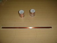
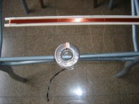
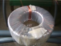
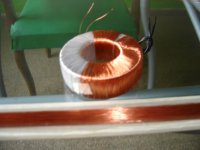
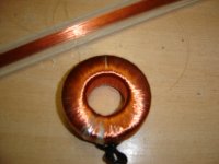
The toroidal mains transformer under construction
Here, some photos of the power transformer at some intermediate stages while rewinding.
Here, some photos of the power transformer at some intermediate stages while rewinding.
Attachments
- Home
- Source & Line
- Analogue Source
- High (Audio) Quality AM Tuner