Listening to the receiver, it sounds clear and pleasant.
The next steep is to make the PCB, when I finished it, I'll post some photos of the finished project. And this moment, I'm designing the power supply unit, with toroidal transformer rewinding for this project, a tube EZ81 for rectifier and with choke input filter.
There was a thread telling me that as I wanted to go away, and I returned, and to do it I must find the door, yeah, I found it, but it was a revolving door and as in The Three Stooges films, I came back again ;-D
Last edited:
Osvaldo, very nice work. Always I wanted to do something similar, but my knowledge it prevent me. I'm just audio lover; DIY projects and medicine.
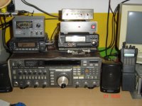
I see that there's a Yaesu amateur radio and I guess sos. I have a colleague who is also a doctor and amateur radio, CX3AN Beto, maybe you know him. Greetings and congratulations on the project, which to my knowledge is unattainable.
I see that there's a Yaesu amateur radio and I guess sos. I have a colleague who is also a doctor and amateur radio, CX3AN Beto, maybe you know him. Greetings and congratulations on the project, which to my knowledge is unattainable.
Osvaldo, very nice work. Always I wanted to do something similar, but my knowledge it prevent me. I'm just audio lover; DIY projects and medicine.
I see that there's a Yaesu amateur radio and I guess sos. I have a colleague who is also a doctor and amateur radio, CX3AN Beto, maybe you know him. Greetings and congratulations on the project, which to my knowledge is unattainable.
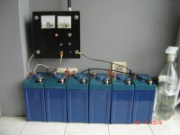
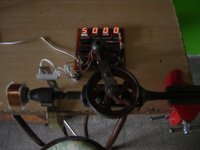
Yes, I'm ham since 1987, LW1DSE. I don't know him. Here are my radios and the power source.
Attachments

OK, thank you, although the las May we had only 4 or 5 days of full sunny, the rest only rain, clouds, fog and mist. 25 days without Rha‼
(I must to use a usual charger to maintain the batteries alive).
Also, not in the photos, I have a fridge operated from the 12V supply.
(I must to use a usual charger to maintain the batteries alive).
Also, not in the photos, I have a fridge operated from the 12V supply.
I am still not convinced that the AM detector uses both diodes.
Yes, boy. I do uses the diode. I could see an advantage in about 6 dB in the recovered audio, respect to the diodes in parallel. Note that the second IF transformer has none of the ends grounded for RF signals, then both are live. I want to post an oscillogram, but I haven't a signal generator, and normal air signals varies too quickly for my camera can take a good detailed photo.
Also, as a tube diode has a relatively high internal resistance, the positive side of the signal that one of lets out, then the other catches it.
Believe me, it works pretty fine‼
I suspect that adding a scope probe will disturb the circuit, as your AM detector works at quite high impedances.
I can see that one diode (EBF89 pin 7) will conduct when the grounded (via R8 1M) end of the secondary is negative and the other end is positive. What I can't see is why the other diode will conduct when the situation is reversed. If it really does work, then all I can think is that stray capacitance somehow provides a grounded virtual centre tap for the secondary.
I can see that one diode (EBF89 pin 7) will conduct when the grounded (via R8 1M) end of the secondary is negative and the other end is positive. What I can't see is why the other diode will conduct when the situation is reversed. If it really does work, then all I can think is that stray capacitance somehow provides a grounded virtual centre tap for the secondary.
The oscilloscope doesn't disturb the circuit, as I always used it connecting the prove to the cathode of the follower. Respect to the high impedance, you are right, it works at about 1MΩ as I told in the above paragraphs, following the book's suggestions: decrease all I can the AC and DC loading of the diode. But future decreasing the resistive part, becomes the parasitics (Mainly capacitances) relevant and disturb the idea.
Look at this. If the lower diode conducts, it makes it with some resistance, so, the entire secondary transformer is maintained at somewhat positive voltage above ground. This positive voltage is catched by the second diode, the one added at the live side of the secondary. Also what you said are partially true, because the diodes have some capacitance and some resistance (Ignore inductances at this frequency), so there exists some AC currents though the diodes.
Look at this. If the lower diode conducts, it makes it with some resistance, so, the entire secondary transformer is maintained at somewhat positive voltage above ground. This positive voltage is catched by the second diode, the one added at the live side of the secondary. Also what you said are partially true, because the diodes have some capacitance and some resistance (Ignore inductances at this frequency), so there exists some AC currents though the diodes.
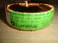
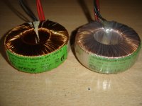
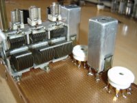
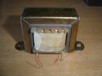
Still more photos for this project: the choke input while being winding, and the transformers, one of the the secondary was dismantled to give place to the 220+220V secondary, still not completed.
The choke is composed of 5000 turns in a bobbin for lam. 42 (14*20mm) of 0.15mm wire diammeter, for a 22Hy 30mA inductor. Air gap is 2 * 0.3mm wide.
The choke is composed of 5000 turns in a bobbin for lam. 42 (14*20mm) of 0.15mm wire diammeter, for a 22Hy 30mA inductor. Air gap is 2 * 0.3mm wide.
Attachments
As much as know, high bandwidth AM reception only possible when receiving local stations, because of the roll off the AM broadcast, for example 5kHz in North America, 4.5kHz in Europe. Those locals are easiest and best to receive with simple "crystal detector" radio.
Ok, I think I am beginning to get it. The extra diode compensates for the relatively high value of the 1M ground leak. Without the diode, the secondary would tend to float up to a positive voltage. I think my mistake was in thinking that the extra diode gave you full-wave rectification (hence +6dB), when it actually helps to repair the half-wave rectification given by the other diode.Osvaldo de Banfield said:Look at this. If the lower diode conducts, it makes it with some resistance, so, the entire secondary transformer is maintained at somewhat positive voltage above ground. This positive voltage is catched by the second diode, the one added at the live side of the secondary.
Given that you have a triode, an infinite impedance detector might be better.
Ok, I think I am beginning to get it. The extra diode compensates for the relatively high value of the 1M ground leak. Without the diode, the secondary would tend to float up to a positive voltage. I think my mistake was in thinking that the extra diode gave you full-wave rectification (hence +6dB), when it actually helps to repair the half-wave rectification given by the other diode.
Given that you have a triode, an infinite impedance detector might be better.
Well, boy, excellent. I believe we are understanding each. Respect with the infinite impedance detector, some people has talked about it, but as I wrote in the firsts paragraphs, I wanted to try some new ideas, so I applied them to my receiver.
I suspect that this forum is perhaps the non ideal place to talk about radios, although I had placed same posts in other more specific sites, but (obviously) with much less impact.
Also, I can't promise nothing, but this weekend I'll try to take a couple of snapshots of the oscillogram, with and without the second diode, so you can compare the behaviour, and take your own conclusions.
This is a thing of beauty. I hope this project is all you hoped it would be.
Thanks for your comments.
Many thanks, Kevin. I feel flattered with your words.Very nice, not a lot I can add until I read through all of the detail, but it looks like fun.
Any further updates? Will you do a PCB at some point?
Kevin: as the project is still under development, the PCB will be the last steep to take. Currently, I'm working in the power supply, a toroidal transformer partially rewind (Secondaries) and the inductor for the choke input rectifier.
The project is working with a temporary power supply, but the running voltage is too high for this tubes, +275V. So the final project will feed with 180/200VDC, a more reasonable one. The main rectifier will be a EZ81, and a second one 6AL5 will provide the negative bias for the circuit. I bought the wire for the secondary (0.15mm diammeter) by an internet supply called Mercado Libre (Something like Ebay) but local for Argentina, but the wire still isn't at my hands.
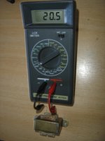
Here are some photos of the inductor designed and finished.
I also want to take advantage of this post, and ask where may I upload two short videos, about 5 second each, to show DF96 and the other participants, the behavior of the detector with and without the above mentioned second detector diode.
Many thanks of your interest in my project. The next project still in the folder, is an entire FM receiver, with MPX recover, all using vacuum tubes.
Attachments
...the roll off the AM broadcast, for example 5kHz in North America, ...
The maximum allowable received audio bandwidth in North America is 10 kHz.
The maximum allowable received audio bandwidth in North America is 10 kHz.
I believe you did a mistake. The audio bandwidth is fixed at the transmitter, and here in Argentina appears to be also, 10KHz. But at the receiver side, you may put the bandwidth you want, 5, 10, or inclusive 20KHz, In the last case, you will listen to 2 or more stations, but is is allowable to do such a thing. And in the first, you will lose the high frequencies of the audio spectrum.
In fact, the first attempt inmy receiver, was to use a 20KHz T filter, but beating between adjacent channels became it unsuccessful, then I migrate to the 10KHz illustrated above. There was a time I thought to use 12KHz in this filter too.
I believe you did a mistake. The audio bandwidth is fixed at the transmitter...
Yep, and mine are fixed at 10 kHz following the North American standard NRSC-AM mask. As this reply is typed I'm watching female voice hit that limit on a spectrum analyzer. The tuner is an Inovonics 520 broadcast monitor.
The best AM sound would probably shock many here accustomed to the usual noisy 80-3500 Hz receivers available. Few-to-no broadcasters aim for that best thought.
- Home
- Source & Line
- Analogue Source
- High (Audio) Quality AM Tuner