Hi Osvaldo,
congratulate on this construction, very nice build.
I didn't follow this thread from beginning and just want to say something about AM and receiver concept.
Did You maybe try SDR (Software Defined Radio) receivers?
If not, take some time and try, you will be surprised how simple and incredible good that can work!
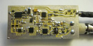
I made several prototypes for SDR receivers (and transmitters also) and I get extraordinary good results for such simple construction. With few ICs you can get reception quality in order of almost all commercial analog transceivers (Yeasu, Kenwood, Icom etc) and on top of that via software in PC you can demodulate any kind of modulation or filter signal with insane characteristics, for example you can apply BP filter of 400th order to signal!
Regarding AM, with SDR you can easily control reception/demodulation bandwidth, standard is 10kHz but you can demodulate as much as your A/D converter can do, for example up to 96kHz of bandwidth with 192ksps audio card.
There are several commercial broadcasting stations which transmit AM signal with 20kHz bandwidth and that sound really good. I also tested with SDR transmitter and receiver "HiFi" transmission on HF frequency range and that sounds almost likes classical FM transmission on VHF range!
I'm attaching photo one of my SDR prototypes.
More on that here:
ZMSDR V3 testiranje YU3MA
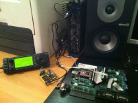
On second photo is shown my first SDR prototype on breadboard made many years ago. Believe me that I did'n find sound difference in reception compared to Icom 706MKII! Just imagine how good SDR can work with more advanced electronic and fast A/D converters ...
If you want to try LIVE reception, check this:
http://websdr.ewi.utwente.nl:8901
congratulate on this construction, very nice build.
I didn't follow this thread from beginning and just want to say something about AM and receiver concept.
Did You maybe try SDR (Software Defined Radio) receivers?
If not, take some time and try, you will be surprised how simple and incredible good that can work!
I made several prototypes for SDR receivers (and transmitters also) and I get extraordinary good results for such simple construction. With few ICs you can get reception quality in order of almost all commercial analog transceivers (Yeasu, Kenwood, Icom etc) and on top of that via software in PC you can demodulate any kind of modulation or filter signal with insane characteristics, for example you can apply BP filter of 400th order to signal!
Regarding AM, with SDR you can easily control reception/demodulation bandwidth, standard is 10kHz but you can demodulate as much as your A/D converter can do, for example up to 96kHz of bandwidth with 192ksps audio card.
There are several commercial broadcasting stations which transmit AM signal with 20kHz bandwidth and that sound really good. I also tested with SDR transmitter and receiver "HiFi" transmission on HF frequency range and that sounds almost likes classical FM transmission on VHF range!
I'm attaching photo one of my SDR prototypes.
More on that here:
ZMSDR V3 testiranje YU3MA
On second photo is shown my first SDR prototype on breadboard made many years ago. Believe me that I did'n find sound difference in reception compared to Icom 706MKII! Just imagine how good SDR can work with more advanced electronic and fast A/D converters ...
If you want to try LIVE reception, check this:
http://websdr.ewi.utwente.nl:8901
Attachments
Last edited:
@yu3ma:
Thanks a lot for your concepts.
Several years ago, I listened about a digital IC that makes all the functios of a superhet receiver, but with algorithms. Perhaps the system you're talking about is an upgrade of this one. Say, for example, the mix between the incoming signal and the osc output was doing using the classical formulae that can be found in any book. Similar design with the IF, RF, detector, etc.
But all this stuff is in the antipodal of what I like.
First, I couldn't never understand how a processor work, and how to program it to do as I want.
Second, I currently prefer to play with tubes/valves and real circuits, over a black box with tents of pins.
Please, also note that the circuit I designed has some differences from standard circuits, and that I like too much to play making my RF coils and calculus.
In any case, thanks again for reading and participating in my thread.
Hi,
The simple fact is FM stereo is vastly superior to AM.
You can make AM better but your chasing your tail.
Comparatively AM will never get near FM.
Any attempt at "hifi" AM seems to me pointless.
Though FWIW many old tuners has good AM sections.
rgds, sreten.
You obviously have never heard a McKay-Dymek tuned to a good station via a good external antenna. The sound quality potential of a proper AM station heard through a proper AM tuner easily out-performs any of the one-chip FM receivers that are found in Big Box stores today.
Even my McIntosh MR-74, given a good station (CBC 540) sounds better on AM than your typical Home Theatre receiver does in stereo FM being stuffed with a massively compressed signal. Of course I don't know what you are being fed for signal back in the UK.
Last edited:
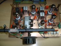
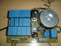
Finals upgrades and details in the tuner. An upgrade in the power supply. I got a new bank of MKP capacitors from scrapped apparatus, and then, the PS is now completed.

A new ferrite bar, the original was 8mm diameter, this new is 12mm, and the same length, 208mm. The improvement is notable, when in the AGC there was -8V with the original, now there are -9V. Less turns drops the resistance of the wire, improving the Q, and the large the cross section, more force lines are captured by the rod, so, more signal induced.

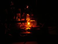
Finally, the tuner in the darkness, showing the neon voltage stabilizer (Reference) and the ECL82's heater.

A new ferrite bar, the original was 8mm diameter, this new is 12mm, and the same length, 208mm. The improvement is notable, when in the AGC there was -8V with the original, now there are -9V. Less turns drops the resistance of the wire, improving the Q, and the large the cross section, more force lines are captured by the rod, so, more signal induced.
Finally, the tuner in the darkness, showing the neon voltage stabilizer (Reference) and the ECL82's heater.
Attachments
Looks absolutely great Osvaldo! Interesting that a loop stick antenna change would provide as much improvement as it does. Can you loosely couple a long wire antenna to the loop stick or is there too much electrical interference for this to work well at your location?
I guess the AGC levels are pretty high which means there is plenty of signal present for a good SNR.
I know you have some good local broadband AM in your neck of the woods, around here a few clear channel stations might have a bit more bandwidth, but most radios aren't good enough to tell.
I have an old Atwater Kent radio receiver chassis (1932 vintage superhet) that I restored some years ago, it works extremely well but is very susceptible to electrical interference due to the intended use of a long wire antenna. Audio bandwidth is about 5kHz.
You obviously have never heard a McKay-Dymek tuned to a good station via a good external antenna. The sound quality potential of a proper AM station heard through a proper AM tuner easily out-performs any of the one-chip FM receivers that are found in Big Box stores today.
<snip>
And sadly he won't have the opportunity to, having recently moved on to the radio free spirit in the sky. 🙁
Looks absolutely great Osvaldo! Interesting that a loop stick antenna change would provide as much improvement as it does. Can you loosely couple a long wire antenna to the loop stick or is there too much electrical interference for this to work well at your location?
Yes, it is possible, but as the tuner has tuned RF stage, it is plenty of gain (The RF stage gains theoretically about 20 times although not measured yet) and surely it will became overloaded easily. Plus it, the tuner is not conceived for DXing, but for pleasant listening. From this, the carefully design of the entire set, mainly the audio detection.
I guess the AGC levels are pretty high which means there is plenty of signal present for a good SNR.
Surely. Also note that the AGC line breaks at some low signal level, giving the maximum amplification from the RF stage, idea borrowed from older tube TV sets.
I know you have some good local broadband AM in your neck of the woods, around here a few clear channel stations might have a bit more bandwidth, but most radios aren't good enough to tell.
Yes, there are some good audio quality and signal level strenght at my location. Also, some lower AM emmisions, and some lower power clandestine AM´s whose audio and signal strenght is very poor.
I have an old Atwater Kent radio receiver chassis (1932 vintage superhet) that I restored some years ago, it works extremely well but is very susceptible to electrical interference due to the intended use of a long wire antenna. Audio bandwidth is about 5kHz.
Long wires are mainly for DXing (From DX, distance unknown), but this kind of receivers has inherent details for this working properly. For example, high impedance RF input, and sometimes two IF's stages with manual gain control and or AGG, and in some other cases, two RF tuned stages, and in some instances, a xtal narrow band filter in the IF stage(s).
Many thanks again for your warm concepts.
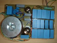
Some weeks ago, the power toroidal transformer became short circuited in the high voltage secondary. I wound it using bifilar 0.18mm enameled copper wire, but it appears that:
1.- The isolation between wires is not sufficient to sustain an entire secondary voltage or;
2.- The loops that was formed when passing the H shaped tool containing the wire through the hole of the core, in the wire, caused a breakage of the insulation enamel in the wire, and although it supported some time (2 years), it definitively fault.
The short circuit was not a real one, it has all the half winding resistance, so although the transformer ran very hot, it still had some output voltages. Then, the primary was OK. The, I unwound the low voltage (Heaters) windings, the bias winding, and the plastic insulation. Once the faulted secondary was at hand, I cut it using an cutting pliers and saved it to recycle the copper.
The new secondary was made using the same wire (0.18mm) but this time in single. The job, obviously was doubled, demanding about four day, not exclusively dedicated to it ( I also slept, ate, etc.). Both sides of the rectifier's plate was equalized in voltage (the trafo has about 10T per volt, so it is easy to tune it to 0VAC between them, wiring temporarily in anti-series or series opposed, not in the normal additive series). The ohmic resistance difference was in the ohm range, which from this point of view is negligible.
Once the HV secondary was tested about 10 minutes, then the low voltage secondaries were wound again, using the same wire. Some time before, the trafo was ready, and placed again in the PSU board. The tuner is now playing again powerful. Here two pics of the old and the new traffo, with the output leads re-positioned in a more properly way.
Attachments
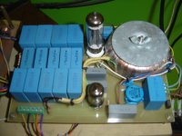
This thread has been started about five years ago. I continue listening to the tuner dayly. Some minor changes I did to it. One is to replace the tunning knob to one used in old transmitters with a self made speed reduction. It has a double effect, the inner one is a direct shaft driver while the outer one has a 10:1 angular movement reduction improving fine tunning. The audio output capacitor has been changed from 1ųF to 3.3ųF @ 100V.
Finally the neon regulator failed to start firing and then I replace with a new unit of larger size. I used a panel 220V neon with socket and resistor removed. Its firing voltage is a bit lower than the original, so the feedback resistor from the regulator has also been updated.
Finally the neon regulator failed to start firing and then I replace with a new unit of larger size. I used a panel 220V neon with socket and resistor removed. Its firing voltage is a bit lower than the original, so the feedback resistor from the regulator has also been updated.
Attachments


- Home
- Source & Line
- Analogue Source
- High (Audio) Quality AM Tuner