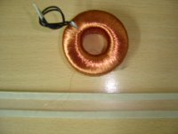
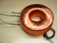
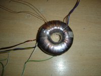
Here are there some photos of the finished high voltage secondary, now ready to receive the lower voltage heater’s windings.


As a bonus data, here are some values of the transformer's parameters:
Measurements made over original transformer as it was:
----------------------------------------------------
Primary voltage................................: 220 V
Secondary voltage............................: 12 V
Secondary current............................: 4 A
Total primary power..........................: 50 VA
Inductance of the primary..................: 8 H
Inductance of the secondary..............: 58 mH
Leakage inductance of primary............: 6.5 mH (1)
Capacitance between coils.................: 440 pF
Resistance of primary coil...................: 46 Ω
Number of turns of secondary winding...: 115 T
Secondary wire diameter:...................: 0.8 mm (2)
(1) Secondary shorted.
(2) Into two bifilar windings and paralleled.
Actual turns per volt ratio: T/V = 115T/12V = 10 T/V
SCu (Copper area in secondary wind.) = 2 * (0.8mm/2)²/π = 1mm² and the current density J is about 4A/mm².
Measurements made over original primary:
---------------------------------------
(Once the 12V secondary has been removed)
Total core plus primary height..............: 26 mm (3)
Internal diameter available…................: 33 mm (3)
External diameter..............................: 74 mm (3)
Magnetic MLT ..................................: 160 mm (4)
MLT = 2 * [26mm + (74mm - 33mm].....: 93 mm
(3) Includes isolation tape.
(4) This is the magnetic mean length turn inside the core, not the wire's MLT!
Requisites for my transformer:
---------------------------
Heaters power:
EF89.................: 6.3V 0.2A;
ECH81................: 6.3V 0.3A;
EBF89................: 6.3V 0.3A;
EABC80..............: 6.3V 0.5A;
ECC82 * 2..........: 6.3V 1.2A;
EZ81.................: 6.3V 1.0A;
6AL5.................: 6.3V 0.3A.
--------------
Total heaters........: 6.3V 3.8A.
For future margin or modifications, I'll use 5A. Note that rectifier will use an own secondary, biased at cathode's potential, but its power drain is, of course, included in the transformer power capability.
Heater's power.........: 6.3V * 5A = 31.5W*
Current drawn in DC..: 40mA
Power DC bus...........: 250V * .04A = 10W
Total transformer.......: 32W + 10W = 42W
then I will use a standard 50VA illumination transformer.
Re-computing of the transformer’s windings:
-----------------------------------------
Voltage at primary..: 220 V
Voltage at S3........: 6.3 V
Current of S3........: 1 A
Voltage at S2........: 220 V
Current of S2........: 0.04 A
Voltage at S1........: 6.3 V
Current of S1......:.. 5 A
S1 is the main heater's winding, S2 is the +B one, and S3 will the rectifier's independent heater winding.
n[S1] = T/V * ES1 = 10 T/V * 6.3V = 63T.
n[S2] = T/V * ES2 = 10 T/V * 240V * 2 = 4800T in 2 bifilar windings.
n[S3] = T/V * ES3 = 10 T/V * 6.3V = 63T.
I've estimated a loss of about 30V in the rectifier's drop, the internal transformer resistance and the inductor DCR. Then 220V at the desired +B bus plus this 30V gives the 250V at the transformer's secondary. As I will use choke input filter, then the 220VRMS when rectified and filtered will be about 220V * 0.9 ≈ 200VDC at the filter's output.
Copper wire diameters can be computed from the current they must let to flow and the current density of the original transformer's secondary (You may also use your own J, but a value too high or too low will give inconveniently high DCR or too high center hole usage, respectively.). Ergo:
Ø[S1] = 1.13√(IS1/J) = 1.13 √(1A/4A/mm²) = 0.56 mm --> .65 mm
Ø[S2] = 1.13√(IS2/J) = 1.13 √(.04/4A/mm²) = 0.113mm --> .15 mm
Ø[S3] = 1.13√(IS3/J) = 1.13 √(5A/4A/mm²) = 1.26 mm --> 1.5 mm
Once finished S2, I could measure over the insulator tape 30mm * 25mm, with a new MLT of 2 * 30mm + 2 * 25mm = 110mm ÷ .11m.
The length of wire for the secondary are estimated:
λS2 = MLT * n[S1] = .1m * 2400T ....= 240 m
λS1 = MLT * n[S2] = .11m * 63T .....= 6.93 m
λS3 = MLT * n[S3] = .11m * 63T .....= 6.93 m
In both heater windings, I'll round up to 7m.
Also, having the resistivity Γ of the wire in Ω/m, you can also check the winding's DC resistances:
DCRS1 = λS1 * Γ[S1] = 7m * 0.053 Ω/m ..= 0.37 Ω
DCRS2 = λS2 * Γ[S2] = 240m * 1 Ω/m .......= 240 Ω
DCRS3 = λS3 * Γ[S3] = 7m * 0.01 Ω/m ....= 0.07 Ω
The voltage drops in the internal wire resistances can be written:
ΛVS1 = DCRS1 * IS1 = .37Ω * 1A.......... = 0.37 V
ΛVS3 = DCRS3 * IS3 = .07Ω * 5A.......... = 0.35 V
The low voltage heater's winding resistance’s are low but no negligible (the voltage drops are under 0.4V), thus a future update will be needed (a couple of turns will be added to compensate them). But, in the main bias, it is of no significance. Let's check if the internal drop is within the estimated. Also take into account that this resistance corresponds to a half secondary only:
ΛVS2 = IS2 * DCRS2 = 20mA * 240Ω = 4.8V
Note (also for purists) that I take the worst case DC current in place of the RMS current, somewhat lesser because each half winding conducts half the AC period and the waveform is a half wave rectified sinusoidal whose DC current is about 1/ã times I if don't remember bad. In any case, this drop is well under the worst case estimated.
Measurements made over my rewinding secondary transformer:
-----------------------------------------------------------
High voltage (Plate to plate)...............................: 512 V (5)
Resistance of the high voltage sec. winding...........: 458 Ω
Resistance of the primary winding........................: 46 Ω*
Inductance of the high voltage winding (P to P).....: 37 H
Inductance of the primary..................................: 6.5 H
Primary leakage inductance.................................: 6 mH (6)
Secondary leakage inductance.............................: 35 mH (7)
Capacitance between coils .................................: 670 pF (8)
(Note final resistance somewhat below the 240Ω * 2 = 480Ω above estimated)
(5) Under no load condition.
(6) Both secondaries (3 wires) shorted together.
(7) Both primary ends (2 leads) shorted together.
(8) Both ends of the coils (pri. and sec.) shorted together respectively.
This data will be updated when I finished the two reminder secondaries.
As final note, PLEASE HAVE A HAND IN YOUR POCKET WHEN MANIPULATING LETHAL HIGH VOLTAGES USUALLY PRESENT IN VALVE/TUBE CIRCUITS.
Attachments
Some smaller upgrades
I had done certain upgrades to the project. As I want to run it at +180VDC, and the bench supply has +275V (Slightly overvoltageing the RF pentodes suggested to work with up to 250V), and I must to rewind the transformer because once finished it drops to floor making it unusable, I must to re-design the series regulator to work with only 75V plate to cathode. Then between the tube candidates I found an ECL82, whose pentode section wired as triode is the new series pass element and the triode is the new cathode follower for the audio filter. But as the regulator only needed to readjust the bias preset, the follower must be entirely re-designed (transcoductance of ECL82's triode is more than twice the ECC82 one, and then the output impedance offered to the filter was incorrect presenting a +4dB overvoltage at the higher end of the audio bandpass) to meet both input and output impedances matching and to get the filter properly terminated. Here are two photos of the new prototype, and soon the new schematic will be posted.
Also some smaller caps was used to decouple the circuits between them.
Attachments
Wow, very cool Osvaldo, it looks like a very sophisticated tuner, and nicely built. Sorry to hear about the power transformer getting dropped, do you have to rewind the whole thing or just some of the windings?
No, entirely new. Primary and secondary, as all windings become damaged. But now it is history, now the rewinding is being finished again. A high amount of patience and few grams of copper wire only were needed.
Thanks for your interest in this project.
Thanks for your interest in this project.
Thanks to Mooly that helped in editing the trafo data, a serious mistake was found, now corrected.
Last edited:
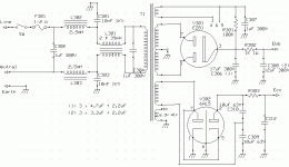
Screen regulator upgrade
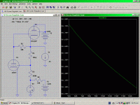
This is the new screen regulator for the AM Tuner Project, still under development.
As the double triode ECC82 has been replaced (modifying the circuit) by a triode pentode ECL82, and in order to use the European set of tubes, the circuit has been redesigned, although its spirit is the same.
Now, the pentode section has been strapped as a triode, and a great improvement has been obtained. Compare the simulation below with these in previous sketch. This is because two main reasons. One is the bigger tranconductance of the cathode follower stage, more than twice the ECC82’s triode, whic in tur conducts to a lower output impedance at the cathode’s end. The other, is the bigger return factor from the voltage divider, as now the NiCd batteries has been removed and replaced by a negative voltage obtained from the main transformer, rectified with a 6AL5 and then stabilized thanks a neon pilot lamp, letting me to have about -65V as the voltage reference. The reminder circuit is the same and continue behaviouring as a upgraded version of the See-Saw classic circuit.
The voltage wanted is about +105V, but in the simulation, the adjusting pot has been omitted giving an error in the output voltage, but the impedance from the circuit is clearly improved.
Attachments
C-Quam
Hi Oslando,
My respect, just browsed few pages of your thread, fantastic and superb.
My question, do you have a stereo broadcasting on AM in Argentina with C-Quam topology, if you do have, are you going to built a C-Quam decoder?
Cheers
Pascal
VK2IHL/XV2PN
Hi Oslando,
My respect, just browsed few pages of your thread, fantastic and superb.
My question, do you have a stereo broadcasting on AM in Argentina with C-Quam topology, if you do have, are you going to built a C-Quam decoder?
Cheers
Pascal
VK2IHL/XV2PN
C-Quam
Hi Osvaldo
My respect, just browsed few pages of your thread, fantastic and superb.
My question, do you have a stereo broadcasting on AM in Argentina with C-Quam topology, if you do have, are you going to built a C-Quam decoder?
Cheers
Pascal
VK2IHL/XV2PN
Hi Osvaldo
My respect, just browsed few pages of your thread, fantastic and superb.
My question, do you have a stereo broadcasting on AM in Argentina with C-Quam topology, if you do have, are you going to built a C-Quam decoder?
Cheers
Pascal
VK2IHL/XV2PN
Thanks for your concepts about my project.
I must clarify that the tittle refer to the audio quality, its appearance is still ugly until I make the PCB, but this will be the last step.
I'm almost sure that no one stereo AM here . I listen about that system, but never I listen it, and in fact, AM and FM bands are super populated of clandestine and low power local radios that it would be impossible to listen them properly.
I must clarify that the tittle refer to the audio quality, its appearance is still ugly until I make the PCB, but this will be the last step.
I'm almost sure that no one stereo AM here
. I listen about that system, but never I listen it, and in fact, AM and FM bands are super populated of clandestine and low power local radios that it would be impossible to listen them properly.Transformer is finished‼
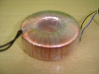
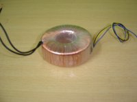
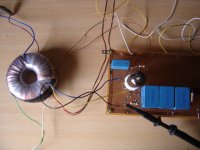
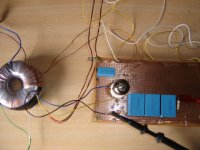
Last weekend I finished the transformer. It has several hours of patience, but it is now finished, and working. Although, it has been redesigned and moves to capacitor input at the filter, not inductor how I wanted from the start of the project. Whence it can be deduced that the working time is less as the output voltage at the high voltage secondary is lower. But as I must to do it twice, then, I must to stop it here. Now, some pics of the finished transformer and the (very ugly‼) prototype of the power supply, still under construction. Also, the tuner itself has been reworked, getting id from the NiCd battery to here used to bias part of the circuit.
Last weekend I finished the transformer. It has several hours of patience, but it is now finished, and working. Although, it has been redesigned and moves to capacitor input at the filter, not inductor how I wanted from the start of the project. Whence it can be deduced that the working time is less as the output voltage at the high voltage secondary is lower. But as I must to do it twice, then, I must to stop it here. Now, some pics of the finished transformer and the (very ugly‼) prototype of the power supply, still under construction. Also, the tuner itself has been reworked, getting id from the NiCd battery to here used to bias part of the circuit.
Attachments
Some measurements made in the supply. the current ripple has been measures inserting a 10Ω 1W resistor in the center tap of the transformer. The second oscillogram is the ripple at the -110V line (voltage doubler) and the third is the same at the main output capacitor, the 3 * 4.7µF blue units. They had rescued from scrapped devices. Next to them, the output voltages.
Soon the schematic and the new calculus.
Soon the schematic and the new calculus.
Attachments

As I said above, the transformer has been modified in order to reduce the number of turns, as I had to do it twice because the first time, once finished the high voltage secondary, it drops to the floor and became useless. So, for those who want to follow my procedure, here are some data I collected and measured in my transformer. In the first part, I present the data collected from the original transformer, then the new calculus and in the third part, data measured in the transformer, and finally the transformer under normal use in the tuner.
Measurements made over original transformer as it was:
-----------------------------------------------------
Primary voltage...........................: 220 V
Secondary voltage......................: 12 V
Secondary current......................: 4 A
Total primary power....................: 50 VA
Inductance of the primary..............: 8 H
Inductance of the secondary..........: 58 mH
Leakage inductance of primary........: 6.5 mH (1)
Capacitance between coils.............: 440 pF
Resistance of primary coil...............: 46 W
Number of turns of secondary winding...: 115 T
Secondary wire diameter:...................: 0.8 mm (2)
(1) Secondary shorted.
(2) Into two bifilar windings and paralleled.
Actual turns per volt ratio: T/V = 115T/12V » 10 T/V
SCu (Copper area in secondary wind.) = 2 * (0.8mm/2)²/π = 1mm² and the current density J is about 4A/mm².
Measurements made over original primary:
---------------------------------------
(Once the 12V secondary has been removed)
Total core plus primary height.................: 26 mm (3)
Internal diameter available…....................: 33 mm (3)
External diameter..................................: 74 mm (3)
Magnetic MLT ......................................: 160 mm (4)
MLT = 2 * [26mm + (74mm - 33mm)/2].....: 93 mm
(3) Includes isolation tape.
(4) This is the magnetic mean length turn inside the core, not the wire's MLT!
Requisites for my transformer:
-----------------------------
Heaters power:
EF89.................: 6.3V 0.2A;
ECH81...............: 6.3V 0.3A;
EBF89................: 6.3V 0.3A;
EABC80..............: 6.3V 0.5A;
ECC82 * 2..........: 6.3V 1.2A;
EZ81.................: 6.3V 1.0A;
6AL5.................: 6.3V 0.3A.
--------------
Total heaters........: 6.3V 3.8A.
For future margin or modifications, I'll use 5A. Note that rectifier will use an own secondary, biased at cathode's potential, but its power drain is, of course, is included in the transformer power capability.
Heater's power.......: 6.3V * 5A = 31.5W
Current drawn in DC..: 40mA
Power DC bus.........: 240V * .04A = 10W
Total transformer....: 32W + 10W = 42W
then I will use a standard 50VA illumination transformer.
Re-computing of the transformer’s windings:
------------------------------------------
As the space in the core is limited and the thinner wires can’t support safely high voltages in a bifilar winding, I’ll redo the calculus in order to make the
Filter input with capacitor, as opposite than the original idea of to use choke input, and then, save space in the core. The voltage at the ouput of the filter will be roughly:
E(DC) = √2 E(RMS)
Whence, inverting the equation, and to get about 240VDC at the output, I need that:
E(RMS) = E(DC) / √2
The rectifier’s drop can be estimated from the graphs in the data sheet from the FAPESA’S book (The old Argentina factory of Philips) in page 205 for the EZ81 double diode, where I saw that it is about 6V for near of 30mA. I also know the DC loss in the inductor 20V, then I need:
E(RMS) = (E(DC) / √2) + E(L) + E(EZ81) = (240V / √2) + 21V + 6V = 197V
Then, the output voltage is chosen in about 200V.
To get the negative voltages necessary to biasing some stages of the tuner, I’ll use a secondary whose output will be doubled using both sections of a 6AL5 of about:
E(RMS) = (E(DC) / 2√2) + 2 * E(6AL5) = (100V / 2√2) + 2 * (2V) = 39.4V
Once again, I choose a 45V at the transformer’s secondary. Which will be about -110VDC at the doubler’s output. Again, the voltage drop at the estimated current has been read from the data sheet.
As a resume, I need from the transformer that:
Input voltage at P1.................: 220 V
Voltage of S4.......................: 45 V
Current at S4.......................: 0.01 A
Voltage of S3.......................: 6.3 V
Current of S3.......................: 1 A
Voltage of S2.......................: 200 V
Current of S2.......................: 0.03 A
Voltage of S1.......................: 6.3 V
Current of S1.......................: 5 A
115T
Number of turn per volt: t = ------ = 10 T/V
12V
n[P] = t * Ep = 10 T/V * 220V = 2200Turns.
n[S1] = t * ES1 = 10 T/V * 6.3V = 63T.
n[S2] = t * ES2 = 10 T/V * 200V * 2 = 4000T in two bifilar windings.
n[S3] = t * ES3 = 10 T/V * 6.3V = 63T.
n[S4] = t * ES4 = 10 T/V * 45V = 450T.
ф[P] = 1.13√(IP/J) = 1.13 √(.25A/4A/mm²) = 0.282 mm --> 0.28 mm
ф[S1] = 1.13√(IS1/J) = 1.13 √(1A/4A/mm²) = 0.56 mm --> 0.65 mm
ф[S2] = 1.13√(IS2/J) = 1.13 √(.015/2A/mm²) = 0.098 mm --> 0.12 mm
ф[S3] = 1.13√(IS3/J) = 1.13 √(5A/4A/mm²) = 1.26 mm --> 1.5 mm
ф[S4] = 1.13√(IS3/J) = 1.13 √(.01A/4A/mm²) = 0.056 mm --> 0.12 mm
For easier of manual winding, the wire of .12mm will be replaced by a .18mm, also in my stock.
For the heater’s winding, and also for easy manual winding, I will use two thinner wires in parallel of the same area together. So if I use a wire whose diameter is 1/√2 times the value calculated, then the net copper area will be the same. Then:
ф[S3r] = 1.13√(IS3/J) = 1.13 √(5A/8A/mm²) = 0.893 mm --> .9 mm
where I took it into account doubling the current density J.
Estimating about 2 mm the net usage of the primary, I will have over the core a mean length turn of 2 * (20mm + 24mm) or 88mm.
Once finished the primary, I measured over it the following parameters:
Primary inductance.................: 5 H
Primary resistance .................: 46 Ω
Height over the winding...........: 27 mm
Width...................................: 20 mm
Now I consider a secondary width S2 of 3mm. Then, the MLT is now of 2 * 27mm + 2 * 20mm = 94mm (I rounded up 100mm).
Also, when finished, I suppose that while winding S1 this will measure over it 3mm more, then 30mm * 23mm, and its MLT is of 2 * 30mm + 2 * 23mm = 104mm = .11m.
I will neglect the S3’s thickness because it will be few turns of a thinner wire. Ergo, the MLT of is also S1 to that of S2 or 0.11m.
Finally, the heater’s secondary for the rectifier EZ81, I can estimate other 3mm in the outer side and 6 in the inner, then the perimeter will be 33mm * 30mm, and the new MLT is* 2 * 33mm + 2 * 30mm = 126mm or .13m.
Now I can estimate the length of the wires used:
λP = MLTP * n[P] = .09m * 2200T......= 198 m;
λS2 = MLTS2 * n[S2] = .1m * 2000T....= 200 m;
λS1 = MLTS1 * n[S3] = .11m * 63T......= 7 m;
λS4 = MLTS4 * n[S4] = .13m * 450T....= 58.5 m;
λS3 = MLTS3 * n[S1] = .13m * 63T......= 8.2 m.
Having wire’s resistivity, I can calculate the DC resistance of each winding:
DCRP = λP * Γ[P] = 200m * .25Ω/m .......= 50 Ω;
DCRS1 = λS1 * Γ[S1] = 8.2m * .053Ω/m.....= 0.44 Ω;
DCRS2 = λS2 * Γ[S2] = 200m * 1.4Ω/m .....= 280 Ω (Per plate);
DCRS3 = λS3 * Γ[S3] = 7m * .01Ω/m ........= 0.07 Ω;
DCRS4 = λS4 * Γ[S4] = 58.5m * 1.14Ω/m ..= 67 Ω.
If also I have the current flowing through the wires, I can compute the resistivity loss in them:
ΔVP = DCRP * IP = 50Ω * 250mA.......= 13 V;
ΔVS1 = DCRS1 * IS1 = .44Ω * 1A..........= 0.44 V;
ΔVS2 = DCRS2 * IS2 = 280Ω * 15mA......= 4.2 V (loss in each half wind.);
ΔVS3 = DCRS3 * IS3 = .07Ω * 5A..........= 0.35 V;
ΔVS4 = DCRS4 * IS4 = 67Ω * 10mA........= 0.67 V.
The high voltage winding loss is in the normal loss, but heaters will be compensated adding some extra turns, aand for the primary, the loss is important, then I will re-compute it:
n[P'] = t * Ep' = 10 e/V * (220V - 13V)= 2070 T; and
λP' = MLTP' * n[P] = .09m * 2070T....= 187 m.
Voltage doubler design:
----------------------

As I can read in chapter 30 page 1174 and associated graphs from Radiotron book by Langford Smith, where the author wrote about rectifiers and voltage multipliers, the value of the capacitors conforming the full wave doubler, it must satisfy the requirement of woRlC > 300 to get a final value near 2√2E(RMS).
The load of the supply from the tuner is low and can be estimated:
Ecc 100V
Rl = ----- = ------ = 33KΩ
Ic 3mA
Solving the above equation for the capacitance, I get:
300 300
C309 & C310 > --------- = -------------------- = 14.5µF
wo * Rl 2pi * 100Hz * 33KΩ
I can try two units rescued from wasted apparatus, whose values are 10µF @ 63V, y and eventually add a second mesh with C311.
Output filter capacitor C306:
----------------------------

Proceeding in a way similar to the above, I can design the main rectifier circuit. From the family of curves in page 1173 of the previously cited book, the value of the output capacitor must satisfy that woRlC > 100 to get an output voltage near to √2E(RMS) en la salida.
The load resistance is:
Ebb 240V
Rl = ----- = ------ = 12KΩ
Ib 20mA
Whence:
100 100
C306 > --------- = ------------------- = 13.3µF
wo * Rl 2pi * 100Hz * 12KΩ
Then I'll use 3 capacitors labeled 4.7µF @ 300VDC, and I'll add to them an extra cap of 2.2µF @ 300VDC.
Now, rearranging the equation, I have:
woRlC = 2pi * 100Hz * 12KΩ * (3 * 4.7µF + 2.2µF) = 122
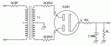
From the data sheet (FAPESA tube manual) for EZ81 in page 205, I get an approximation for the diode's resistance, Rd:
-- Ed 5V
Rd ÷ ---- = ------ = 200Ω
Id 25mA
Transformer's secondary resistance was estimated above and was about 280Ω, and primary's was 50Ω, and if I transfer it to the secondary, I have:
N2 2000T
DCRPs = DCRP * ---- = 50Ω * -------- = 48Ω
N1 2070
The total resistance seen from each anode is:
Rs = DCRPs + DCRS2 = 280Ω + 48Ω = 328Ω
With this data, I refer to Radiotron, page 1175, I calculate some parameter of the rectifier, using his own nomenclature:
^ --
rd = 0.88 Rd = 0.88 * 200Ω = 176Ω
^ ^
Rs = Rs + rd = 328Ω + 176Ω = 504Ω
With all this information I can compute the ripple at the output. To do it, and from page 1177 I get:
^
|rd| = rd / 0.93 = 176Ω / .93 = 190Ω
|Rs| = Rs + |rd| = 328Ω + 190Ω = 518Ω
|Rs| 518Ω
------ % = ------ = 4.3%
RL 12KΩ
From the graph 30.9 in page 1176 I get the value of the ripple percentage respect to the DC is 0.7% approximately.
Then:
|Er| = 0.7% * 240V = 1.7V
To get the peak to peak value, I make the conversion approximating the waveform to a saw tooth, and I have:
Erpp = |Er| * √12= 1.7V * √12 = 5.9Vpp
In the prototype, and in a photo below, I got about 12Vpp of ripple, which is a bit high. Then I plan to add a second mesh, using post RC filtering.
I accept a maximum voltage drop in a resistor R302 of 20V. If by it flow the 20mA of the receiver the maximum admissible is:
V(R302) 20V
R302 = -------- = ------- = 1KΩ
Il 20mA
and the loss of power in it:
W(R302) = V(R302) * Il = 20V * 20mA = 400mW
then I choose a resistor of 1KΩ @ 1W.
In the other hand I have 3 capacitors of 3.3µF of the same type and ratings that those of 4.7µF, and two more of 2.2µF. I will use it in the second mesh. The ripple attenuation ripple is:
|Ero| 1 1
α = ------- = ----------------------- = -----------------------------------
|Eri| (w * R302 * C308) + 1 (2π * 100Hz * 1000Ω * 14µF) + 1
= .107
Then, the ripple is reduced the 10% from that at the input.
Some tests to the finished transformer:
--------------------------------------
Primary Inductance.........................: 4.7 H
Primary Leackage Inductance............: 6.2 mH (*)
Primary Resistance..........................: 46 Ω
Secondary Inductance S2 (total).......: 15.6 H
Leackage Inductance S2..................: 13.2 mH (*)
Secondary Resistance S2 (total)........: 230 Ω
Secondary voltage S2......................: 200 V
Secondary Inductance S3.................: No measurable
Secondary Resistance S3 (apx.).........: 0.55 Ω
Secondary voltage S3......................: 7 V
Secondary Inductance S4.................: 0.27 H
Secondary Leackage Inductance S4....: 10.4 mH (*)
Secondary Resistance S4 (apx.).........: 80 Ω
Secondary voltage S3.......................: 47 V
Secondary Voltage S1......................: 6.8 V
Secondary Inductance S1.................: No measurable
Secondary Resistance S1 (apx.).........: 1 Ω
Capacitance from primary to S2.........: 0.67 nF
Capacitance from S2 to S3...............: 0.52 nF
Capacitance from primary a S3..........: 0.3 nF
Capacitance from primary a S4..........: 0.12 nF
Capacitance from S2 to S4...............: 0.14 nF
Capacitance from S2 a S3................: 0.18 nF
Capacitance from S1 a S3................: 0.12 nF
(*) Winding shorted at its ends.
Measurements made over original transformer as it was:
-----------------------------------------------------
Primary voltage...........................: 220 V
Secondary voltage......................: 12 V
Secondary current......................: 4 A
Total primary power....................: 50 VA
Inductance of the primary..............: 8 H
Inductance of the secondary..........: 58 mH
Leakage inductance of primary........: 6.5 mH (1)
Capacitance between coils.............: 440 pF
Resistance of primary coil...............: 46 W
Number of turns of secondary winding...: 115 T
Secondary wire diameter:...................: 0.8 mm (2)
(1) Secondary shorted.
(2) Into two bifilar windings and paralleled.
Actual turns per volt ratio: T/V = 115T/12V » 10 T/V
SCu (Copper area in secondary wind.) = 2 * (0.8mm/2)²/π = 1mm² and the current density J is about 4A/mm².
Measurements made over original primary:
---------------------------------------
(Once the 12V secondary has been removed)
Total core plus primary height.................: 26 mm (3)
Internal diameter available…....................: 33 mm (3)
External diameter..................................: 74 mm (3)
Magnetic MLT ......................................: 160 mm (4)
MLT = 2 * [26mm + (74mm - 33mm)/2].....: 93 mm
(3) Includes isolation tape.
(4) This is the magnetic mean length turn inside the core, not the wire's MLT!
Requisites for my transformer:
-----------------------------
Heaters power:
EF89.................: 6.3V 0.2A;
ECH81...............: 6.3V 0.3A;
EBF89................: 6.3V 0.3A;
EABC80..............: 6.3V 0.5A;
ECC82 * 2..........: 6.3V 1.2A;
EZ81.................: 6.3V 1.0A;
6AL5.................: 6.3V 0.3A.
--------------
Total heaters........: 6.3V 3.8A.
For future margin or modifications, I'll use 5A. Note that rectifier will use an own secondary, biased at cathode's potential, but its power drain is, of course, is included in the transformer power capability.
Heater's power.......: 6.3V * 5A = 31.5W
Current drawn in DC..: 40mA
Power DC bus.........: 240V * .04A = 10W
Total transformer....: 32W + 10W = 42W
then I will use a standard 50VA illumination transformer.
Re-computing of the transformer’s windings:
------------------------------------------
As the space in the core is limited and the thinner wires can’t support safely high voltages in a bifilar winding, I’ll redo the calculus in order to make the
Filter input with capacitor, as opposite than the original idea of to use choke input, and then, save space in the core. The voltage at the ouput of the filter will be roughly:
E(DC) = √2 E(RMS)
Whence, inverting the equation, and to get about 240VDC at the output, I need that:
E(RMS) = E(DC) / √2
The rectifier’s drop can be estimated from the graphs in the data sheet from the FAPESA’S book (The old Argentina factory of Philips) in page 205 for the EZ81 double diode, where I saw that it is about 6V for near of 30mA. I also know the DC loss in the inductor 20V, then I need:
E(RMS) = (E(DC) / √2) + E(L) + E(EZ81) = (240V / √2) + 21V + 6V = 197V
Then, the output voltage is chosen in about 200V.
To get the negative voltages necessary to biasing some stages of the tuner, I’ll use a secondary whose output will be doubled using both sections of a 6AL5 of about:
E(RMS) = (E(DC) / 2√2) + 2 * E(6AL5) = (100V / 2√2) + 2 * (2V) = 39.4V
Once again, I choose a 45V at the transformer’s secondary. Which will be about -110VDC at the doubler’s output. Again, the voltage drop at the estimated current has been read from the data sheet.
As a resume, I need from the transformer that:
Input voltage at P1.................: 220 V
Voltage of S4.......................: 45 V
Current at S4.......................: 0.01 A
Voltage of S3.......................: 6.3 V
Current of S3.......................: 1 A
Voltage of S2.......................: 200 V
Current of S2.......................: 0.03 A
Voltage of S1.......................: 6.3 V
Current of S1.......................: 5 A
115T
Number of turn per volt: t = ------ = 10 T/V
12V
n[P] = t * Ep = 10 T/V * 220V = 2200Turns.
n[S1] = t * ES1 = 10 T/V * 6.3V = 63T.
n[S2] = t * ES2 = 10 T/V * 200V * 2 = 4000T in two bifilar windings.
n[S3] = t * ES3 = 10 T/V * 6.3V = 63T.
n[S4] = t * ES4 = 10 T/V * 45V = 450T.
ф[P] = 1.13√(IP/J) = 1.13 √(.25A/4A/mm²) = 0.282 mm --> 0.28 mm
ф[S1] = 1.13√(IS1/J) = 1.13 √(1A/4A/mm²) = 0.56 mm --> 0.65 mm
ф[S2] = 1.13√(IS2/J) = 1.13 √(.015/2A/mm²) = 0.098 mm --> 0.12 mm
ф[S3] = 1.13√(IS3/J) = 1.13 √(5A/4A/mm²) = 1.26 mm --> 1.5 mm
ф[S4] = 1.13√(IS3/J) = 1.13 √(.01A/4A/mm²) = 0.056 mm --> 0.12 mm
For easier of manual winding, the wire of .12mm will be replaced by a .18mm, also in my stock.
For the heater’s winding, and also for easy manual winding, I will use two thinner wires in parallel of the same area together. So if I use a wire whose diameter is 1/√2 times the value calculated, then the net copper area will be the same. Then:
ф[S3r] = 1.13√(IS3/J) = 1.13 √(5A/8A/mm²) = 0.893 mm --> .9 mm
where I took it into account doubling the current density J.
Estimating about 2 mm the net usage of the primary, I will have over the core a mean length turn of 2 * (20mm + 24mm) or 88mm.
Once finished the primary, I measured over it the following parameters:
Primary inductance.................: 5 H
Primary resistance .................: 46 Ω
Height over the winding...........: 27 mm
Width...................................: 20 mm
Now I consider a secondary width S2 of 3mm. Then, the MLT is now of 2 * 27mm + 2 * 20mm = 94mm (I rounded up 100mm).
Also, when finished, I suppose that while winding S1 this will measure over it 3mm more, then 30mm * 23mm, and its MLT is of 2 * 30mm + 2 * 23mm = 104mm = .11m.
I will neglect the S3’s thickness because it will be few turns of a thinner wire. Ergo, the MLT of is also S1 to that of S2 or 0.11m.
Finally, the heater’s secondary for the rectifier EZ81, I can estimate other 3mm in the outer side and 6 in the inner, then the perimeter will be 33mm * 30mm, and the new MLT is* 2 * 33mm + 2 * 30mm = 126mm or .13m.
Now I can estimate the length of the wires used:
λP = MLTP * n[P] = .09m * 2200T......= 198 m;
λS2 = MLTS2 * n[S2] = .1m * 2000T....= 200 m;
λS1 = MLTS1 * n[S3] = .11m * 63T......= 7 m;
λS4 = MLTS4 * n[S4] = .13m * 450T....= 58.5 m;
λS3 = MLTS3 * n[S1] = .13m * 63T......= 8.2 m.
Having wire’s resistivity, I can calculate the DC resistance of each winding:
DCRP = λP * Γ[P] = 200m * .25Ω/m .......= 50 Ω;
DCRS1 = λS1 * Γ[S1] = 8.2m * .053Ω/m.....= 0.44 Ω;
DCRS2 = λS2 * Γ[S2] = 200m * 1.4Ω/m .....= 280 Ω (Per plate);
DCRS3 = λS3 * Γ[S3] = 7m * .01Ω/m ........= 0.07 Ω;
DCRS4 = λS4 * Γ[S4] = 58.5m * 1.14Ω/m ..= 67 Ω.
If also I have the current flowing through the wires, I can compute the resistivity loss in them:
ΔVP = DCRP * IP = 50Ω * 250mA.......= 13 V;
ΔVS1 = DCRS1 * IS1 = .44Ω * 1A..........= 0.44 V;
ΔVS2 = DCRS2 * IS2 = 280Ω * 15mA......= 4.2 V (loss in each half wind.);
ΔVS3 = DCRS3 * IS3 = .07Ω * 5A..........= 0.35 V;
ΔVS4 = DCRS4 * IS4 = 67Ω * 10mA........= 0.67 V.
The high voltage winding loss is in the normal loss, but heaters will be compensated adding some extra turns, aand for the primary, the loss is important, then I will re-compute it:
n[P'] = t * Ep' = 10 e/V * (220V - 13V)= 2070 T; and
λP' = MLTP' * n[P] = .09m * 2070T....= 187 m.
Voltage doubler design:
----------------------
As I can read in chapter 30 page 1174 and associated graphs from Radiotron book by Langford Smith, where the author wrote about rectifiers and voltage multipliers, the value of the capacitors conforming the full wave doubler, it must satisfy the requirement of woRlC > 300 to get a final value near 2√2E(RMS).
The load of the supply from the tuner is low and can be estimated:
Ecc 100V
Rl = ----- = ------ = 33KΩ
Ic 3mA
Solving the above equation for the capacitance, I get:
300 300
C309 & C310 > --------- = -------------------- = 14.5µF
wo * Rl 2pi * 100Hz * 33KΩ
I can try two units rescued from wasted apparatus, whose values are 10µF @ 63V, y and eventually add a second mesh with C311.
Output filter capacitor C306:
----------------------------
Proceeding in a way similar to the above, I can design the main rectifier circuit. From the family of curves in page 1173 of the previously cited book, the value of the output capacitor must satisfy that woRlC > 100 to get an output voltage near to √2E(RMS) en la salida.
The load resistance is:
Ebb 240V
Rl = ----- = ------ = 12KΩ
Ib 20mA
Whence:
100 100
C306 > --------- = ------------------- = 13.3µF
wo * Rl 2pi * 100Hz * 12KΩ
Then I'll use 3 capacitors labeled 4.7µF @ 300VDC, and I'll add to them an extra cap of 2.2µF @ 300VDC.
Now, rearranging the equation, I have:
woRlC = 2pi * 100Hz * 12KΩ * (3 * 4.7µF + 2.2µF) = 122
From the data sheet (FAPESA tube manual) for EZ81 in page 205, I get an approximation for the diode's resistance, Rd:
-- Ed 5V
Rd ÷ ---- = ------ = 200Ω
Id 25mA
Transformer's secondary resistance was estimated above and was about 280Ω, and primary's was 50Ω, and if I transfer it to the secondary, I have:
N2 2000T
DCRPs = DCRP * ---- = 50Ω * -------- = 48Ω
N1 2070
The total resistance seen from each anode is:
Rs = DCRPs + DCRS2 = 280Ω + 48Ω = 328Ω
With this data, I refer to Radiotron, page 1175, I calculate some parameter of the rectifier, using his own nomenclature:
^ --
rd = 0.88 Rd = 0.88 * 200Ω = 176Ω
^ ^
Rs = Rs + rd = 328Ω + 176Ω = 504Ω
With all this information I can compute the ripple at the output. To do it, and from page 1177 I get:
^
|rd| = rd / 0.93 = 176Ω / .93 = 190Ω
|Rs| = Rs + |rd| = 328Ω + 190Ω = 518Ω
|Rs| 518Ω
------ % = ------ = 4.3%
RL 12KΩ
From the graph 30.9 in page 1176 I get the value of the ripple percentage respect to the DC is 0.7% approximately.
Then:
|Er| = 0.7% * 240V = 1.7V
To get the peak to peak value, I make the conversion approximating the waveform to a saw tooth, and I have:
Erpp = |Er| * √12= 1.7V * √12 = 5.9Vpp
In the prototype, and in a photo below, I got about 12Vpp of ripple, which is a bit high. Then I plan to add a second mesh, using post RC filtering.
I accept a maximum voltage drop in a resistor R302 of 20V. If by it flow the 20mA of the receiver the maximum admissible is:
V(R302) 20V
R302 = -------- = ------- = 1KΩ
Il 20mA
and the loss of power in it:
W(R302) = V(R302) * Il = 20V * 20mA = 400mW
then I choose a resistor of 1KΩ @ 1W.
In the other hand I have 3 capacitors of 3.3µF of the same type and ratings that those of 4.7µF, and two more of 2.2µF. I will use it in the second mesh. The ripple attenuation ripple is:
|Ero| 1 1
α = ------- = ----------------------- = -----------------------------------
|Eri| (w * R302 * C308) + 1 (2π * 100Hz * 1000Ω * 14µF) + 1
= .107
Then, the ripple is reduced the 10% from that at the input.
Some tests to the finished transformer:
--------------------------------------
Primary Inductance.........................: 4.7 H
Primary Leackage Inductance............: 6.2 mH (*)
Primary Resistance..........................: 46 Ω
Secondary Inductance S2 (total).......: 15.6 H
Leackage Inductance S2..................: 13.2 mH (*)
Secondary Resistance S2 (total)........: 230 Ω
Secondary voltage S2......................: 200 V
Secondary Inductance S3.................: No measurable
Secondary Resistance S3 (apx.).........: 0.55 Ω
Secondary voltage S3......................: 7 V
Secondary Inductance S4.................: 0.27 H
Secondary Leackage Inductance S4....: 10.4 mH (*)
Secondary Resistance S4 (apx.).........: 80 Ω
Secondary voltage S3.......................: 47 V
Secondary Voltage S1......................: 6.8 V
Secondary Inductance S1.................: No measurable
Secondary Resistance S1 (apx.).........: 1 Ω
Capacitance from primary to S2.........: 0.67 nF
Capacitance from S2 to S3...............: 0.52 nF
Capacitance from primary a S3..........: 0.3 nF
Capacitance from primary a S4..........: 0.12 nF
Capacitance from S2 to S4...............: 0.14 nF
Capacitance from S2 a S3................: 0.18 nF
Capacitance from S1 a S3................: 0.12 nF
(*) Winding shorted at its ends.
Attachments

Last edited:
Hi Osvaldo,
Lots of progress over the past few weeks. I particularly like the line filter implementation, it should really help to keep line born RF noise out of the tuner.
6AL5 were somewhat common as bias rectifiers, wondering if in FW doubler configuration their peak current capability is sufficient - is the winding resistance sufficient to limit the current to a safe value particularly during the first few cycles of charging current?
Hi Osvaldo,
Lots of progress over the past few weeks. I particularly like the line filter implementation, it should really help to keep line born RF noise out of the tuner.
6AL5 were somewhat common as bias rectifiers, wondering if in FW doubler configuration their peak current capability is sufficient - is the winding resistance sufficient to limit the current to a safe value particularly during the first few cycles of charging current?
Many many thanks for your interest.
6AL5 has a DC current capability of 9mA per section. Current drained will be under 3mA. As it has a common heater string with the rest of the set, it will be slowly charging during warm up at current limited because of low temperature of its cathodes. Secondary voltage is only 47V, so I don't believe it will fail.
In my Regenerative Receiver, some years ago published here, I also use a line filter. Mercury and sodium vapor lamps in the street illumination cause lots of noise conducted by the wiring itself. And in a toroidal transformer, it is very difficult to add a screen between primary and secondaries, as it is in EI counterparts, without causing a shorted turn failure.
Continue sending your comments, they are welcomed; and continue improving your health.
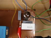
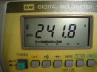
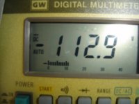
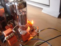
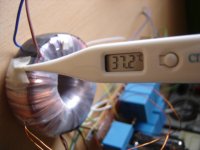
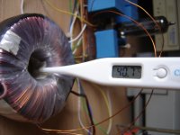
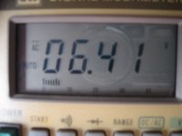
First firing and live hours of my trafo.
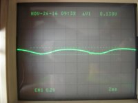
Here some pics from my power supply for the tuner. Observe main parameters, and check also how they agree with the calculae below.
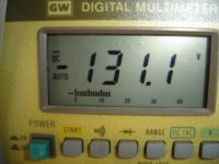
First, the operation temperature after 3 hours of playing, no air flow nor wind:


Then, main heater voltage under full load:

Perfect!
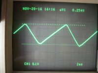
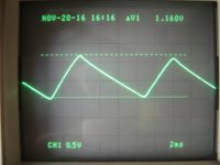
Now, the mains ripple after and before the CRC filter:


Please note that this oscilloscope's original proves had an automatic x10 pin reader, as the probes had been replaced, the reading are no longer multiplied, the make your own x10 multiplication on voltage readings.
Here some pics from my power supply for the tuner. Observe main parameters, and check also how they agree with the calculae below.
First, the operation temperature after 3 hours of playing, no air flow nor wind:
Then, main heater voltage under full load:
Perfect!
Now, the mains ripple after and before the CRC filter:
Please note that this oscilloscope's original proves had an automatic x10 pin reader, as the probes had been replaced, the reading are no longer multiplied, the make your own x10 multiplication on voltage readings.
Attachments

Last edited:
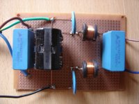
Line filter
Here are the mains line filter, as a prototype only. Very ugly, no?

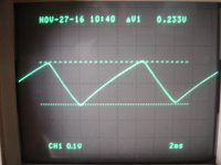
Now, line current viewed inserting an 1Ω 1W resistor in series with the neutral, and using the scope as differential input to eliminate common mode signals at both ends. After and before filtering.


Here are the mains line filter, as a prototype only. Very ugly, no?
Now, line current viewed inserting an 1Ω 1W resistor in series with the neutral, and using the scope as differential input to eliminate common mode signals at both ends. After and before filtering.
Attachments


- Home
- Source & Line
- Analogue Source
- High (Audio) Quality AM Tuner