Here there are two short videos (less than 10sec each) showing the receiver's signal at the follower's cathode, with and without the auxiliary diode. The second channel of the oscilloscope, is grounded, and sited at the center of the AM signal, say, when the modulation index would become -1 or -100%, no instantaneous carrier amplitude.
This video shows the signal with the second diode still wired in the circuit. Note the high negative amplitude and the presence of high audio components in the signal. (Unfortunately, my camera didn't take good photos at very near target respect to the len, so the focus is poor, but sufficient to see the details).
This other looks the same signal, but with the diode un-wired.
The oscilloscope setting stayed untouched between films, which can also be checked in the read out in the bottom of the CRT screen. Also, no other control of the tuner has been altered. Note audio signal in Spanish, as it has been taken from a local AM station, Radio Mitre AM 790 in Buenos Aires.
You can also see, that the entire signals displaces downward with the diode removed. It's cause is because the coupling capacitor can't pass DC, then at the grid side the DC becomes almost zero (a small contact potential exists there), then, the higher the negative hemicycle amplitude, the more negative the mean DC voltage it has, and vice versa, which also checks the enhancement in the rectification of the signal.
The maximum allowable received audio bandwidth in North America is 10 kHz.
half of it
Amplitude Modulation/Superheterodyne
"The bandwidth of AM signals can be easily predicted using the now familiar formula: BW = 2 fm. "
where fm = the maximum modulating frequency
"The bandwidth of AM signals can be easily predicted using the now familiar formula: BW = 2 fm. "
where fm = the maximum modulating frequency
Sorry, I could not deduce anything from those videos. They looked fairly similar to me.
Oh, my god‼
OK. Try again, but put on your glasses :-D
Differences are very noticeable, almost for me. Don't for you?
As I remember, the RF bandwidth is twice the frequency modulating the carrier (audio), and at 100% modulation reach one fourth the power at the carrier (half voltage amplitude).

This can be see in this book or any other.
This, independent of legal terms which are outside of my knowledge.
This can be see in this book or any other.
This, independent of legal terms which are outside of my knowledge.
Attachments
Yes, the bandwidth of an AM signal is exactly twice the audio bandwidth - assuming low distortion in the modulator and any subsequent amplifiers. 100% modulation of a single tone means each sideband has half the amplitude (i.e. one quarter the power) of the carrier.
Yes, the bandwidth of an AM signal is exactly twice the audio bandwidth..
That's correct, and the maximum allowable analogue audio bandwidth in North America is 10 kHz for non-IBOC stations.
Attachments
Wikipedia says: "Nowadays in most of the Americas, mediumwave broadcast stations are separated by 10 kHz and have two sidebands of up to ±5 kHz in theory, although in practice stations transmit audio of up to 10 kHz."
AM broadcast is a waste of power, many hundred kilowatts emitted just for the sake of the receivers' simplicity. And the usable information is carried in 25% of the total emitted power.
https://www.gpo.gov/fdsys/pkg/CFR-2006-title47-vol4/xml/CFR-2006-title47-vol4-sec73-44.xml
It seems FCC does not limit below 10.2 kHz. It is the interest of stations not to hang into each others' sideband, probably this is why they limit volunteerly at +/-4.5 or +/-5 kHz. Most receivers do it anyway.
Last edited:
AM carries the baseband information in up to 33% of the total power.lcsaszar said:AM broadcast is a waste of power, many hundred kilowatts emitted just for the sake of the receivers' simplicity. And the usable information is carried in 25% of the total emitted power.
You can always swap a few kW at the transmitter for a few W in thousands of receivers, but where does that get you? Given how technically illiterate the average member of the public is, receiver (and tuning) simplicity seems to be a good thing.
That would require 20kHz bandwith, no such thing.
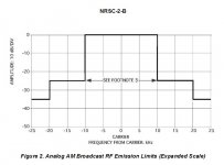
That's the NRSC AM mask son, go outside for a bit.
AM broadcast is a waste of power, many hundred kilowatts emitted just for the sake of the receivers' simplicity.
AM preceded FM by decades. It's maintained for legacy reasons, lack of sufficient FM avails to convert all the AMs and much superior coverage compared to FM. A broadcast license can also be worth tens of millions on its own, few broadcasters return them.
MDCL alleviates a significant portion of the efficiency issues. A guideline is available on the NRSC site linked earlier. When you're paying many thousands a month to power a 50 kW the market responds with solutions.
Interesting. But a little cumbersome with all of those valve stages and IF transformers.
Here's my take. An automatic regenerative receiver using a low distortion impedance detector. The output level remains constant due to the AGC regen adjustment, making the receiver immune to fading. The only inductor is the loop antenna!
Here's my take. An automatic regenerative receiver using a low distortion impedance detector. The output level remains constant due to the AGC regen adjustment, making the receiver immune to fading. The only inductor is the loop antenna!
Attachments

See R6! You can manually adjust the selectivity. Can you do that with a typical superhet? 😀
Bandwidth usefully decreases as stations become quieter, reducing noise.
Bandwidth usefully decreases as stations become quieter, reducing noise.
In America are to many stations on the same frequency, propagation in the day time close to zero, even with the max allowed 50kW, that means local stations. At night are hundreds of stations within reach, not many would provide quality reception, that means again local. For that a crystal detector radio is sufficient. Providing wide bandwidth and the highest sound quality. On the other hand, if one is for talk radio listening there is no need for quality, but a directional antenna is a must , so that means a pocket radio with a ferrite antenna.
With a typical superhet you don't need to keep twiddling with the bandwidth. And won't R6 affect the signal level too?monty78pig said:Can you do that with a typical superhet?
A regenerative set with one tuned circuit will have poor skirt selectivity, so only suitable for listening to strong local stations on a relatively uncrowded band. There is a reason why domestic radio sets moved from regeneration to superhet, despite the extra complexity of a superhet.
With a typical superhet you don't need to keep twiddling with the bandwidth. And won't R6 affect the signal level too?
Well, consider this. When the station gets weaker, regeneration increases, reducing bandwidth. So strong stations can benefit from wide-band reception while weak ones are received with narrow-band to reduce interference and noise.
Look at AGC subsystem based around Q4. You'll see that adjusting R6 only affects the amount of regenerative feedback, while the output level stays constant. Clever, eh 😉 ?
- Home
- Source & Line
- Analogue Source
- High (Audio) Quality AM Tuner