doesn't have a resistor between the input and the ground - You get the input circuit with a very large time constant without fixing level (relative to the ground). Just add a resistor 🙂
OK, added 100k resistor in parallel with C2 (430p).
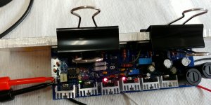
Everything looks good. Amp is stable, Thermally tracking just fine, idle current
stable at 50mA.
Output DC offset is 500mV (and going slowly down, started at 700mV).
Little bit too high for my liking, but I guess that's the problem with symmetrical
designs - they are never 100% symmetrical, hence the offset.
I'll check if I can squeeze bipolar 220uF cap is series with R3 (150 Ohm)
on that board.. It's gonna bit a tough fit.
What is the consensus? Is 500mV too high?
Later in the day will follow with oscilloscope tests.
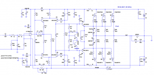
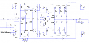
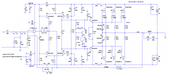
Latest .asc file attached.
Everything looks good. Amp is stable, Thermally tracking just fine, idle current
stable at 50mA.
Output DC offset is 500mV (and going slowly down, started at 700mV).
Little bit too high for my liking, but I guess that's the problem with symmetrical
designs - they are never 100% symmetrical, hence the offset.
I'll check if I can squeeze bipolar 220uF cap is series with R3 (150 Ohm)
on that board.. It's gonna bit a tough fit.
What is the consensus? Is 500mV too high?
Later in the day will follow with oscilloscope tests.
Latest .asc file attached.
Attachments
Last edited:
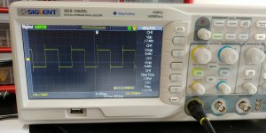
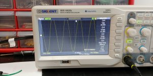
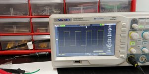
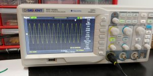
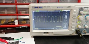
Sinus looks good, but squares have overshoots.
To be tweaked/improved.
Edit: Just noticed, that I installed 82pF caps instead of 47pF on the bases of the drivers (2SC3503/2SA1381).
I guess will revert them to 47pF, and see if that fixes the overshot on square waves.
To be tweaked/improved.
Edit: Just noticed, that I installed 82pF caps instead of 47pF on the bases of the drivers (2SC3503/2SA1381).
I guess will revert them to 47pF, and see if that fixes the overshot on square waves.
Attachments
Last edited:
DC offset will probably get lower with a suitable capacitor in series with R3.
Another thought - add a DC servo. You could use a dual opamp which are typically easier to source than singles are 🙂
Another thought - add a DC servo. You could use a dual opamp which are typically easier to source than singles are 🙂
There are several reasons for this. First, I have never done such a design, the optimal ground plane design requires more study. Second, I tried to follow the signal path of scematics as close as possible, so it's quite short and simple, well separated from the high-current paths. The signal ground is always connected to the PS star point with a separated wire, with this method I achieved a completely noise and hum free design earlier. Third, one of the audio gurus suggested that bring the op-amp rail filtration (100nF) with separated ground track to local star point for maximum stability, so there is a much greater opportunity to use different types of ICs. However, I was also thinking using ground plane.
Last edited:
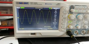
OK, testing with oscilloscope done.
Very easy amp. No problems at all, except the initial 'misunderstanding' with the input resistor.
Idle current stable, and tracking temperature very nicely.
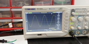
All waves looking perfect.
C8 changed to 220pF. I was incrementally increasing it from 82p to came up with good minimal value, and 220pF it is.
I left C14/C15 at 82pF (my mistake) as is, but they should be 47pF.
See the screenshots.
Next thing - I'll try to fix the DC offset. This can be done by:
a) adding 220uF cap in series with R3
b) using servo
c) matching Q1-Q6 perfectly
I'll try option a) if I can squeeze the cap somewhere on the pcb.
And I'll add back speed-up cap C21 1uF.
Very easy amp. No problems at all, except the initial 'misunderstanding' with the input resistor.
Idle current stable, and tracking temperature very nicely.
All waves looking perfect.
C8 changed to 220pF. I was incrementally increasing it from 82p to came up with good minimal value, and 220pF it is.
I left C14/C15 at 82pF (my mistake) as is, but they should be 47pF.
See the screenshots.
Next thing - I'll try to fix the DC offset. This can be done by:
a) adding 220uF cap in series with R3
b) using servo
c) matching Q1-Q6 perfectly
I'll try option a) if I can squeeze the cap somewhere on the pcb.
And I'll add back speed-up cap C21 1uF.
Attachments

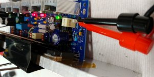
Latest Mini Beast PCB
1uf speed up and 220uF FB capacitors added.
PS: Truly impressive 20 kHz square wave
1uf speed up and 220uF FB capacitors added.
PS: Truly impressive 20 kHz square wave
Attachments

Last edited:
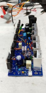
220uF BP cap added. Speed-up cap added.
DC offset is just couple of mV now.
The eagle has landed.
Now I just to need to build 2nd channel, and mount it on the chassis.
========================
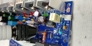
Few things that differ from the schematic:
22 Ohm resistors on CCS bases were skipped in my build.
My pcb was done before they were added.
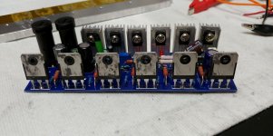
Output devices: FQA40N25 / FQA36P15
In the sim N devices were different.
The source resistors - I used 0.33 Ohm, because I have a lot of them; otherwise would use 0.22 Ohm.
Op-amp: TL071
Catch diodes between rails and output have been added (1N400X).
DC offset is just couple of mV now.
The eagle has landed.
Now I just to need to build 2nd channel, and mount it on the chassis.
========================
Few things that differ from the schematic:
22 Ohm resistors on CCS bases were skipped in my build.
My pcb was done before they were added.
Output devices: FQA40N25 / FQA36P15
In the sim N devices were different.
The source resistors - I used 0.33 Ohm, because I have a lot of them; otherwise would use 0.22 Ohm.
Op-amp: TL071
Catch diodes between rails and output have been added (1N400X).
Attachments
Last edited:
One more thing I discovered I messed up in this build.
In the previous build, I was using FQA27N25 (1500pF Ciss)
and FQA36P15 (2550pF Ciss). So gate stoppers were 120 Ohm for N devices, and 82 Ohm for P devices.
In this build I used FQA40N25, which has 3100pF Cis.
So gate stoppers should be bigger for P device in this case...
The opposite of the previous build.
I incorrectly assumed, that Ciss ratio for these mosfets is the same...
I will measure Ciss on these mosfets, just to confirm the numbers from the datasheet, but it seems like we need here 82 Ohm gate stoppers for N devices, and 100 Ohm for P devices.
Update: Measured Ciss on both N and P devices is about the same: 5000pF.
So gate stoppers should be the same, say 100 Ohm.
Will change these resistors on my board tomorrow.
Last edited:
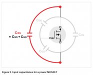
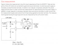
Ciss
Hi Minek,
This figure is not as bad as it seems here because the gate/source capacitance is bootstrapped with a source follower.
If the gm is high, then the variation of the Vgs is pretty small and so the dV/dT is far smaller than if used in common source. I count on about a quarter, so you are only dealing with about 1.2nF, a walk in the park for your driver current. But I'm with you on the gate stoppers, should be higher
with the n devices.
I seem to remember there is a gate stopper calc on this somewhere?
Hugh
I know the _actual_ (effective) Ciss will be much lower, but the _ratio_ most likely will be the same...
The calc is simple: Rg1 * Ciss1 = Rg2 * Ciss2
The calc is simple: Rg1 * Ciss1 = Rg2 * Ciss2
Last edited:
According the datasheets the Ciss of FETs I'm using:
FQA46N15: 2500-3250pF
FQA36P15: 2550-3320pF
Minek, how do you measure the input capacitance of FETs? I found the following method.
FQA46N15: 2500-3250pF
FQA36P15: 2550-3320pF
Minek, how do you measure the input capacitance of FETs? I found the following method.
Attachments
Last edited:

"Currently unavailable". However, I have a similar tester. I think in this case Cg = Cgd + Cgs. Thanks, it will be easier.
Attachments

One thing I'm not sure if we should use the Ciss numbers from the datasheet, or Cg from the measurement..
For Latfets, measured Cg ratio was identical to datasheet's Ciss ratio.
For the 1st amp with FQA, same thing.
For these devices (in 2nd amp), measurement of Cg ratio differs from Ciss ratio from datasheet.
Anyway, in our cases these mosfets are close enough to warrant identical stoppers.
I'll just replace 82 Ohm resistors with 120 Ohm resistors to make them all identical.
Last edited:
I'll just replace 82 Ohm resistors with 120 Ohm resistors to make them all identical.
I'll do that as well.
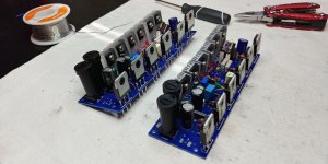
Board for 2nd channel populated.
Gate stoppers on both channels: 120 Ohm for both N & P devices.
Testing to follow.
I forgot to test different op-amps in this amp. Will try to remember when testing 2nd channel.
Gate stoppers on both channels: 120 Ohm for both N & P devices.
Testing to follow.
I forgot to test different op-amps in this amp. Will try to remember when testing 2nd channel.
Attachments
Last edited:
- Home
- Amplifiers
- Solid State
- HexFet Amp Based on Philips AH578 and LMK