Egra, remove the NTC-based bias spreader from the schematic, it's outdated.
I see in the PCB you are using one with LED.
Beautiful board!
I see in the PCB you are using one with LED.
Beautiful board!
Egra, remove the NTC-based bias spreader from the schematic, it's outdated. Beautiful board!
Thank you. You mean this?
Attachments

See post
Unusual amp from 1987
I tested this spreader myself, and it seems to work ok.
Previously, for mosfets I was using spreader with LED (like Valery), but I didn't really test its tempco myself. But I guess you can trust Valery that it also works ok.
Unusual amp from 1987
I tested this spreader myself, and it seems to work ok.
Previously, for mosfets I was using spreader with LED (like Valery), but I didn't really test its tempco myself. But I guess you can trust Valery that it also works ok.
>Thank you. You mean this?
Yes. You were faster than me.
C23 is only needed if you planning to connect temperature sensor by wires.
If sensor is on the board soldered directly, you can skip C23.
Also speed-up cap C16 has been removed.
There is no consensus if it's needed, and at what value. Most likely smaller than 1uF..
You can try with it and without it...
Last edited:
>Thank you. You mean this?
Yes. You were faster than me.
C23 is only needed if you planning to connect temperature sensor by wires.
If sensor is on the board soldered directly, you can skip C23.
Also speed-up cap C16 has been removed.
There is no consensus if it's needed, and at what value. Most likely smaller than 1uF..
You can try with it and without it...
Thanks for the infos. I'm going to modify the PCB.
But I guess you can trust Valery that it also works ok.
Certainly. VHEX+ also has such a spreader and works flawlessly. PS: However if I remember correctly Borys had the original idea.
Last edited:
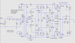
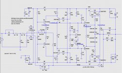
The current sources Q3 and Q4 provide the voltage gain in this circuit. They are controlled at the emitter so that the largest possible bandwidth is attained. Together with the transistors Q1 and Q2, each forms a complementary cascode circuit. One of the simplest and most effective method to eliminating Miller effect.
PS: I have to correct myself. It was jkuetemann not borys
PS: I have to correct myself. It was jkuetemann not borys
Last edited:
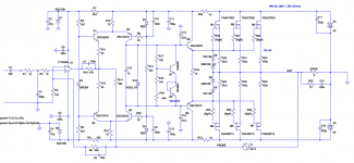
This is my latest schematic and sim. I switched here to 2SA/2SC drivers, but I'm not sure yet what I'm going to use (TTC/TTA or 2SA/2SC)....
Attachments
Last edited:
I switched here to 2SA/2SC drivers, but I'm not sure yet what I'm going to use (TTC/TTA or 2SA/2SC)....
According to my latest motto (anything that causes the signal to have a variable delay is an enemy to beat) 2SK/SAs are better (at least theoretically), they have 4x lower Cob than TTC/TTAs.
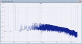
What are those periodically repeating humps over 10kHz in fft spectrum? I have not yet found a way to moderate them. Perhaps the FQAs themselves are the source of this?
Attachments
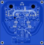
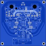
LMK&PHILIPS mini mongrel PCB (transistor+transdiode bias)08202021
LMK&PHILIPS mini mongrel PCB 08202021
LMK&PHILIPS mini mongrel PCB 08202021
Attachments
Last edited:
What was wrong with blue color? 🙂
I love these audiophile input caps size of baby's arm 🙂
Edit: Now it's blue...
I love these audiophile input caps size of baby's arm 🙂
Edit: Now it's blue...
Last edited:
I love these audiophile input caps size of baby's arm 🙂
Like a huge ugly brick. 🙂 In this case, it's slightly smaller. It's a Kemet PPS (Polyphenylene Sulfide) film capacitor. I've used these stuffs in other projects as well with success.
>What are those periodically repeating humps over 10kHz in fft spectrum?
These are harmonics. All (most?) high-bandwidth amps (especially with mosfets) exhibit these.
What do harmonics signify in the FFT spectrum of a signal?
These are harmonics. All (most?) high-bandwidth amps (especially with mosfets) exhibit these.
What do harmonics signify in the FFT spectrum of a signal?
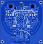
@minek. Today I want to send the PCB to the factory, before that I share the final version of 36V "mini beast".
1. VFETs are FQA46N15/FQA36P15
2. 33Ohm + 220pF snubbers are applied for better safety
3. 500 Ohm trimmer pot decreased to 200 Ohm for easier setting
4. R13 decreased to 15kOhm for better current symmetry of Q1/Q2 and Q3/Q4
5. In bias spreader 2x2n5551 will be used instead of MPSA42s.
Any comments will be appreciated
Attachments
Last edited:
I only have 3 remarks:
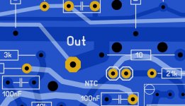
1) 100nF capacitor in Zobel, usually should be bigger (X2 rated) - see this one B32921X2104M000 (that's what I used).
But I guess that's not really critical..
2) the output post, and FB takeout, should NOT be taken from the main fat track between emitters. Currents are not settled on that track.
See image attached.
Feedback track should originate exactly at the output post, not from the fat track between emitters.
This is more important than 1).
3) These 45 Ohm resistors, in real build most likely gonna be 47 Ohm
I see - inspired by Mr Petrov, you changed your signature motto 🙂
Attachments
Last edited:
- Home
- Amplifiers
- Solid State
- HexFet Amp Based on Philips AH578 and LMK