I have always really liked this design. It may have been designed to minimise costs by reducing parts count, but it has some wonderful tricks in it and the masterful connection of the IC is something I have not seen before.
HD
Agree. The unrivaled virtue of this topology is the rich tube-like sound and the complete lack of the usual solid state roughness and dryness.
Minek and egra, there are a few different threads relating to this Philips topology. What are the latest versions of the amplifiers recommended for builders? Are there any built versions yet from this thread?
Is the preference for hexfets over latfets?
Is the preference for hexfets over latfets?
Last edited:
Minek and egra, there are a few different threads relating to this Philips topology. What are the latest versions of the amplifiers recommended for builders? Are there any built versions yet from this thread?
Is the preference for hexfets over latfets?
The latest LATFET version (and closest to original PHILIPS) you can find here. It's stable in all aspects and has excellent sound, has already been built by minek123, tcd1963 and egra. As I know no one has built the HEXFET version yet, but minek did share a great version of it.
I'm building this amp (from this thread) - waiting for PCB to arrive.
Other amps built so far: see 1st posts from these 2 threads (in chronological order):
1) Unusual amps (several amps)
2) Philips Latfet amp (one amp)
In total I built 5 successful amps with this topology, plus a few failed ones 🙂
In sim, hexfets come up slightly better. Many people say Latfets sounds better.
From my experience, I would go with hexfets.
In real life - at least for me - all GOOD amps sound the same.
As far as actual measurements with audio analyzer go, they can't be told apart.
Even quasi 2n3055 amp in this topology sounds/measure the same, up to 15W of power.
Only bad amps have so called 'signature' in my opinion 🙂
So I can't recommend one specific amp - all of them are very good.
LMK, Wiederhold, Philips..
Philips seems to have best selection of PCBs - everybody designed his own 🙂
Last edited:
Superficially similar but is hexfet
This looks like kind of CFA topology. Usually they don't hold low voltage offset at the output, and they need a servo to correct this..
>but minek did share a great version of it.
Actually I have several other, recent versions of this topology, all of them looking great - E.g. version of Bose 1801 amp
looks very promising.
But the truth is, most of them have similar Thd, profile, sound, etc....
So I'm not publishing them.
I also plan to build one suggested by Aksa in this thread.
With vas driven from op-amp rails. Very fast and stable. See post #117.
Last edited:
Thanks for the clarifications!
Would it be feasible to use a quad of TO3 Hitachi laterals on short leads to the PCB in place of the dual die Exicons?
Would it be feasible to use a quad of TO3 Hitachi laterals on short leads to the PCB in place of the dual die Exicons?
Thanks for the clarifications!
Would it be feasible to use a quad of TO3 Hitachi laterals on short leads to the PCB in place of the dual die Exicons?
Why not?
You may need to adjust values of gate stoppers - depending on
the input capacitance of the fets. It was described somewhere in these threads..
And of course use source resistors (0.22) if paralleling fets.
Also you may want to bump up rail voltage, to take advantage of higher power from multiple devices...
Zener resistors will change slightly..
Last edited:
It was described somewhere in these threads..
And of course use source resistors (0.22) if paralleling fets.
"The role of caps on GS is to equalize input capacitance on both devices (P and N). Usually N device has lower capacitance than P device, so some designers ADD extra cap on N device to make them equal. Example: Rod Elliot's P101. If capacitances are not equal - that may cause oscillations.
Another way of dealing with this issue, is by using DIFFERENT gate stoppers, using formula RC = constant, where R is gate stopper resistor, and C is input capacitance of the FET. Adjust R on the both devices, so RC value are equal on upper and lower FETs.
Example: Let's say the 2SJ162 has a gate stopper of 100 Ohm and a gate capacitance of 900pF, the RC time constant is just RgatexCgate=RC time constant, so 100x900x10^-12=90nS. If we want 'balance' we need a resistance on the gate of the 2SK1058 that gives the same time constant. So, Rgate x 600pF = 90nS, solve for Rgate. In this case Rgate needs to be 150 Ohm.
Exicon double die devices: P/N have different capacitance, N device has 900pF LESS input capacitance (I actually measured it to confirm the datasheet) so in this amp, upper Rg=470 Ohm, and lower Rg = 220 Ohm."
Last edited:
Check this out. Similar to your LMK+Philips578 hybrid
Saw this. I did sim Bose (DAUB) amps.
They (except Bose 1800-III, which doesn't sim that great) use traditional VAS (like Philips), and Bose 1801 comes up really good. Better than Philips. Still working on it, but this could be worth building.. But my amp-building-pipeline is kind of full now (3 amps waiting to be built), and soon will have to go back to the office (no more remote work), so this will perhaps wait a little...
Superficially similar but is hexfet
I tried to sim this (with different OS) - Yes, the output offset is not controlled by op-amp, and without servo, it will be too high.
Servo, or manual zero circuit might be in order here.
Thd numbers and FFT profile are so so...
Attachments
OldDIY, you have photographic memory. 🙂🙂🙂🙂
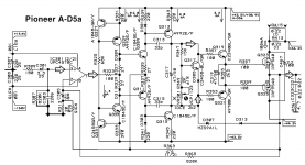
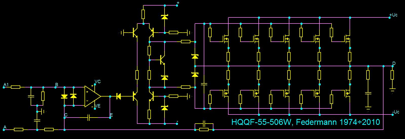
I recognize this amp, and mr Federman, he was active here years ago!
Don't recall if he actually finished it..
I recognize this amp, and mr Federman, he was active here years ago!
Don't recall if he actually finished it..
This is 'normal' Wiederhold '77 amp, from 'unusual amp' thread,
just drawn in different way, so it kind of looks (at the 1st sight) like op-amp + LTP + cascodes.
No drivers - driving fets directly from cascodes. I tried that in one build,
it sounded bad, even though sim and oscilloscope looked good.
just drawn in different way, so it kind of looks (at the 1st sight) like op-amp + LTP + cascodes.
No drivers - driving fets directly from cascodes. I tried that in one build,
it sounded bad, even though sim and oscilloscope looked good.
Last edited:
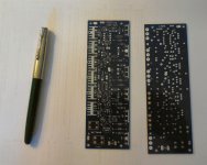
PCBs for the amp from post#2 arrived.
Looks like it's gonna be busy August...
Great! This amp what I really care about. I'm looking forward to the result. Starting to design my PCB for 36V.
- Home
- Amplifiers
- Solid State
- HexFet Amp Based on Philips AH578 and LMK