Tietze & Schenk BA-50M PCB
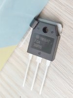
After several weeks (?) of production time, the boards have finally arrived today. No one recommends using VFETs without source resistors, even for single par. Unless I would use an 'auto-bias' circuit. So I'm trying to place the transdiode sensor as efficiently as possible. I will glue it on FET direclty as follows. Glued on heat sink it would not be efficient and fast enough for this, I guess.
This is a "HexFet Amp Based on Philips AH578 and LMK" with 36V supply voltage and single pair FET output. The nickname is Tietze & Schenk BA-50M. The topology was first published in mid 70's by Dr. Tietze and Dr. Schenk as "Breitband Verstärker" i.e. Broadband amplifier (BA), 50W (50), the circuit designed by minek123 (M). Later, I will refer to it so.
Attachments

Last edited:
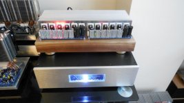
Interesting observation - I just built a new PSU for my amps.
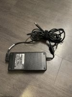
I encased 4 pieces of HP laptop switching PSUs (each of them 19.5V, 12A).
Last year, I used similar PSU bricks to power Alpha Nirvana class A amp. It worked great.
GENUINE HP AC ADAPTER 230W HSTNN-DA12 19.5V 11.8A 609946-001 608432-003 | eBay
The PSU box gives me +/- 20V rails and +/- 40V rails.
I tried to play the latest amp I built from this thread, using this new PSU,
and I can ACTUALLY tell the difference in sound. Previous PSU was a linear
PSU with a toroid transoformer.
With this new PSU, when listening to music (flac) ripped from 80's vinyl record
('Fuerza Major' by Camaro's Gang) I can actually hear subtle vinyl scratches,
that I didn't even know were there!
Also, but I'm less sure about this - the bass might be slightly stronger.
Photo - Amp sitting on top of the new PSU.
Attachments
Last edited:
.. The nickname is Tietze & Schenk BA-50M. The topology was first published in mid 70's by Dr. Tietze and Dr. Schenk as "Breitband Verstärker" i.e. Broadband amplifier (BA), 50W (50), the circuit designed by minek123 (M). Later, I will refer to it so.
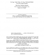
Which edition of the book ? Thanks
>Will try to post the relevant page later if it is of any interest. |
It was posted already in another thread:
Unusual amp from 1987
Maybe you have more/different source info about this topology?
As far as I know it was first published by Faran and Fulks.
See this post:
Unusual amp from 1987
It was posted already in another thread:
Unusual amp from 1987
Maybe you have more/different source info about this topology?
As far as I know it was first published by Faran and Fulks.
See this post:
Unusual amp from 1987
Last edited:
Which edition of the book ? Thanks
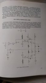
I have to correct what I wrote. This schematic what I refer to can only be found in a later edition of the book (1992?). I have a printed version of the first edition from 70's translated in Hungarian. In this book you can find a single ended (earlier) version of T-S broadband amplifier only. It's similar to LMK, but in this case the emitter current of the first transistor is equal to the output current of the opamp (5-7mA), so this circuit is much more sensitive to the type of IC used.
Attachments
Off topic : what are D2, D3 good for (post189) ?
I don't have the book in my hand right now, but those could be overcurrent protection diodes.
- Home
- Amplifiers
- Solid State
- HexFet Amp Based on Philips AH578 and LMK