..., measurement of Cg ratio differs from Ciss ratio from datasheet.
Agree. FQAs have arrived from mouser today, measuring Cg's show a significant difference compared to datasheet. P FETs Cg are 5530pF, N FETs are 5620pF (Ciss 2500-3300pF in datasheet)
Last edited:
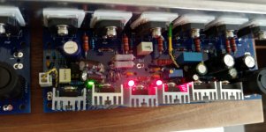
Board for 2nd channel populated.
Gate stoppers on both channels: 120 Ohm for both N & P devices.
Testing to follow.
I forgot to test different op-amps in this amp. Will try to remember when testing 2nd channel.
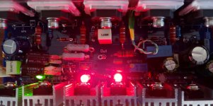
Testing 2nd channel finished.
No surprises - everything work just fine.
0mV output DC offset, perfect waves, just like with the 1st board.
I was checking the temperature of Zener resistors.
In the previous build (#post 1597), these resistors were running hot (100 C), and they were heating up the pcb itself, and all 'neighbor' devices.
They were 1W, but small in size. So this time I used bigger ones (also 1W, but chunkier). Well, they also run at 100 C.
Or do they?
When measuring temperature using small infrared thermometer, it shows 100 C. When using different one - using metal probe, it shows 68 C. Which one to believe?
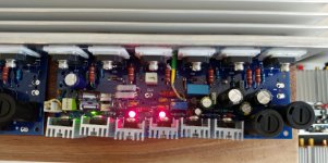
At lower temperatures they both agree, more or less.
I guess metal probe should be more accurate.
Bottom line - the size of resistors doesn't seem to matter..
Didn't test different op-amps, because access to the op-amp is obscured by caps hanging all over it, pcb is too crowded... So I gave up on messing up with op-amps.
TL071 it is.
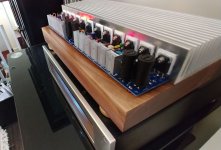
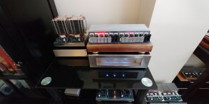
So all electrical work is done, now chassis needs to be made.

Amp completed. Playing music as we speak.
Sounds great, so far 🙂
Very easy amp. No problems and surprises.
Just solder it together, and plug in 🙂
14 transistors + 1 op-amp per channel. So far the "biggest" amp I built.
Sounds great, so far 🙂
Very easy amp. No problems and surprises.
Just solder it together, and plug in 🙂
14 transistors + 1 op-amp per channel. So far the "biggest" amp I built.
Attachments
Last edited:


Thanks Vunce.
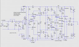
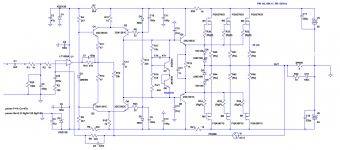
Now, instead of doing one more full "audio test" of the amp, with carefully selected material, here is new approach to CCS design.
It works, but I can't sim it in LTSpice.
Now, instead of doing one more full "audio test" of the amp, with carefully selected material, here is new approach to CCS design.
It works, but I can't sim it in LTSpice.
Attachments
Last edited:
Thanks Vunce.
Now, instead of doing one more full "audio test" of the amp, with carefully selected material, here is new approach to CCS design.
It works, but I can't sim it in LTSpice.
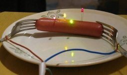
Haha.. you been watching some of Jeri Ellsworth's older videos ? 🙂 There's a video in which she does exactly this. Tasty hotdog afterward too.
This experiment doesn't really work very well here in the UK, 240V cooks things too fast 😉
Update: Been playing this amp for several weeks now, and it's the best amp period.
Very happy with it. Rock solid and stable, great sound and lots of power.
Very happy with it. Rock solid and stable, great sound and lots of power.
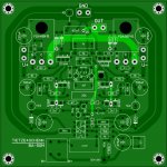
TIETZSCHE & SCHENK BA-50M
Great news. The PCB of downscaled version (36V, single pair FETs) attached. Unfortunately this version much harder to stabilize than LMK one.
PS.: I often see (especially in the case of overseas members) describing the term "period." Always in a positive context. What does it mean exactly. Is this slang?
Update: Been playing this amp for several weeks now, and it's the best amp period.
Very happy with it. Rock solid and stable, great sound and lots of power.
Great news. The PCB of downscaled version (36V, single pair FETs) attached. Unfortunately this version much harder to stabilize than LMK one.
PS.: I often see (especially in the case of overseas members) describing the term "period." Always in a positive context. What does it mean exactly. Is this slang?
Attachments
Last edited:
>I often see (especially in the case of overseas members) describing the term "period." Always in a positive context. What does it mean exactly. Is this slang?
'Period' means 'dot' character at the end of sentence.
Spelling it at the end of sentence (instead or beside of putting the actual '.' sign), exaggerates the whole sentence.
>Unfortunately this version much harder to stabilize than LMK one.
You tried? Or it's just a prediction?
'Period' means 'dot' character at the end of sentence.
Spelling it at the end of sentence (instead or beside of putting the actual '.' sign), exaggerates the whole sentence.
>Unfortunately this version much harder to stabilize than LMK one.
You tried? Or it's just a prediction?
'Period' means 'dot' character at the end of sentence.Spelling it at the end of sentence (instead or beside of putting the actual '.' sign), exaggerates the whole sentence.
Thank you. Now it is clear.
You tried? Or it's just a prediction?
Simulated. Very low phase margin. Or acceptable margins with to high THD. Low power version with single pair FETs seems to have more disadvantages than advantages.
Attachments
Last edited:
That's not right.
In my sim PM was 66, GM: 11
and it was very stable in actual build.
That should not depend on number of output fets.
Actually, in real build - the more fets - the less stable it will be if they are not matched well.
How about without RC snubbers?
If PM was less than 45-50 it may not be stable in real life..
Attachments
Last edited:
That's not right.
In my sim PM was 66, GM: 11
and it was very stable in actual build.
That should not depend on number of output fets.
Actually, in real build - the more fets - the less stable it will be if they are not matched well.
I mean the low power version. Probably caused by the GD snubber. I'm not sure I'll include it in the final version. Nowhere have I seen such protection applied at those who have used these FQA fets.
I would not use them in the initial build, and only add them IF you have oscillations.
These snubbers should be calculated for a specific oscillation frequency, which depends
on many factors (e.g. types of fets)..
These snubbers should be calculated for a specific oscillation frequency, which depends
on many factors (e.g. types of fets)..
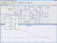
PM of 29 - well below 45 which I consider 'minimum', is not acceptable.
How is it without snubbers?
How is it without snubbers?
- Home
- Amplifiers
- Solid State
- HexFet Amp Based on Philips AH578 and LMK