Alrighty,
So here's the results.
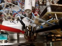
The headphone amp sounds great, a million times better. No hum that i can tell!
So I'm very happy about that. Rick your the man! I didn't even route the input wire from the caps nicely. Also just regular wire not shielded.
I wasn't able to get any change in the dc voltage when i adjusted the trimpot.
I put my terminals on the left and right channel of the headphone jack. Is that correct?
So here's the results.
The headphone amp sounds great, a million times better. No hum that i can tell!
So I'm very happy about that. Rick your the man! I didn't even route the input wire from the caps nicely. Also just regular wire not shielded.
I wasn't able to get any change in the dc voltage when i adjusted the trimpot.
I put my terminals on the left and right channel of the headphone jack. Is that correct?
Attachments
It sounds great? Yay! 
Erm .. umm .. No, you'll have to check it at the op-amp side of the output capacitors -- from there to ground. Odds are the two outputs will be slightly different, but it should be possible to get them both within a few millivolts of zero.
Regards
Erm .. umm .. No, you'll have to check it at the op-amp side of the output capacitors -- from there to ground. Odds are the two outputs will be slightly different, but it should be possible to get them both within a few millivolts of zero.
Regards
Hey Rick,
Yes it sounded very good when I listened to it yesterday through my Grado headphones.
Cheers! I'll have a drink to that.
I don't have any caps on the output.
I was under the impression that your temp compens circuit was used so that we wouldn't need to use electrolytics in the output.
Yes it sounded very good when I listened to it yesterday through my Grado headphones.
Cheers! I'll have a drink to that.
I don't have any caps on the output.
I was under the impression that your temp compens circuit was used so that we wouldn't need to use electrolytics in the output.
So I measured DC voltage at the left and right channel to ground.
I was able to split the difference and get both to read ..017v.
I was able to split the difference and get both to read ..017v.
Another update. I've let it warm up. This changed the dc voltage readings. I tried to adjust, and the closest I could get was .011 and .02 v. the trim pot ran out of adjustability. I have the lid off so it would probably get warmer.
Yes, that was the objective 😉 but if I had Grado's, I probably wouldn't plug them in before confirming that the offset had come in as desired.
11, 17 and 20mV are all within what I would consider reasonable and acceptable (for a circuit that isn't self-correcting -- using an integrator or what not). But since the cover is still off (*good*), and it is headed in a direction that is beyond the compensation range, it might be worth the trouble to give it the 'hair dryer test'. With the blow dryer set on Med or High heat but low Fan, shine it into the chassis for a few 10's of seconds at a time, watching the output offset. That should give a useful indication whether we need to add/change a resistor to extend the pot range.
Do I remember right that you implemented a 10k pot? With the headphones disconnected, let's see what the full adjustment range of the pot is. Then we'll do a little arithmetic to see what change(s) need(s) to be made.
Yes, that was the objective 😉 but if I had Grado's, I probably wouldn't plug them in before confirming that the offset had come in as desired.
11, 17 and 20mV are all within what I would consider reasonable and acceptable (for a circuit that isn't self-correcting -- using an integrator or what not). But since the cover is still off (*good*), and it is headed in a direction that is beyond the compensation range, it might be worth the trouble to give it the 'hair dryer test'. With the blow dryer set on Med or High heat but low Fan, shine it into the chassis for a few 10's of seconds at a time, watching the output offset. That should give a useful indication whether we need to add/change a resistor to extend the pot range.
Do I remember right that you implemented a 10k pot? With the headphones disconnected, let's see what the full adjustment range of the pot is. Then we'll do a little arithmetic to see what change(s) need(s) to be made.
Yes 10k pot. I was able to get the voltage to .045 by a bit if heating.
With the headphones disconnected am I measuring for DC voltage? Just like before?
You might want to put a small amount of isolation resistance (10 to 100 ohms range) between the op amp output and the headphone's jack. It's possible that capacitance in the headphone cable could be making the amplifier oscillate. Be sure the amplifier model you are using can drive a low impedance like that.
Yes, with the headphones disconnected.
So, the offset starts out positive, and increases in the positive direction with heat? Is it approximately the same on both channels? Maybe I didn't get the temperature compensation as right as I thought .. 😱
What offset voltage(s) do you get at the other end of the trimpot?
So, the offset starts out positive, and increases in the positive direction with heat? Is it approximately the same on both channels? Maybe I didn't get the temperature compensation as right as I thought .. 😱
What offset voltage(s) do you get at the other end of the trimpot?
Hey Rick,
I'll have to re check and pay attention to negative or positive.
I'll make some notes and reply. Where should I measure at the trimpot.
On the R2 side or the R3 side? It may be tricky to get my probe on there.
I'll have to re check and pay attention to negative or positive.
I'll make some notes and reply. Where should I measure at the trimpot.
On the R2 side or the R3 side? It may be tricky to get my probe on there.
That's OK -- we can sort the end-of-trimpot voltages indirectly by the effect on the output offset. Also a good thing, since on top of the accessibility issue, those nodes are rather high impedance, so probe loading would probably jinx the measurements.
Last edited:
Hey Rick
So i took some more measurements.
It's hard to make sense of it.
It acts one way without the blow drier and differently when i apply heat for a few secs at a time.
I can get readings at the headphone jack of about R-.017 and L+.016 with the pot adjusted. That's without heating up or warmup.
If i apply heat both sides go negative.
R-.07 L-.04
Once they settle down and max adjustment on the pot the best I can get is R-.025 and L.008v
Also for a split second on startup
R-.2 L .07
Hopefully there's some useful information here.
Last edited:
Sorry I'm slow catching back up to you 😱 These are kind of strange results. Clearly what I thought was a clever design is at least somewhat less clever!
The bump at startup probably can't be tamed without additional circuitry -- a mute approach like we applied to the valve section.
But the others should not take too much trouble to improve a decent bit. But it will take me some more puzzling -- a couple/few days mayhaps, hopefully.
If you can, let it warm up for 5 minutes or so, then measure each output offset (headphones unplugged) at each end of the trimpot.
Cheers
Hey Rick,
With reference to your schematic on post 67. Where would you like me to put my leads to measure?
With reference to your schematic on post 67. Where would you like me to put my leads to measure?
No need to measure at the perfboard just yet. Am still fiddling with LTSpice -- wish I'd've done that earlier, rather than just the back-of-the-bar-napkin approach -- even though it is time consuming (due entirely to my lack of expertise 😱).
All I'd like to measure just now, is the output offset, No Load (headphones unplugged), each channel, first at one end of the trimpot, then at the other. So, just a little table of 4 values. After 5 or so minutes' warm-up is fine; cover off but just natural convection.
Depending on those values and the new secrets that LTSpice exposes, I may want/need another little table of the same four values, with the hair dryer. But let's not worry about that just yet. Thanks.
Regards
Last edited:
Hey Rick,
I've never heard of LTSpice. It's able to calculate values?
I'm sorry to say I'm still not following the "one end of the trimpot first then the other" instruction.
I've never heard of LTSpice. It's able to calculate values?
I'm sorry to say I'm still not following the "one end of the trimpot first then the other" instruction.
You're in for some serious fun! Linear Technology developed it -- pretty sure, thus the 'LT' -- they're now owned by Analog Devices. And it's FREE! 😀
LT Spice
In a bit I'll post what I have so far; there's still a lot to do. (Everything seems to proceed so slowly this time of year .. or, come to think of it, maybe it's this time of life!)
Position the unit so that the trimpot is accessible, if possible, and let it warm-up for 5 minutes or so, headphones unplugged. Then let's measure the output offset at the headphone jack, of each channel, with the trimpot cranked fully CW. Then adjust the trimpot all the way to the fully CCW position, and record that value for each channel.
Sorry about the lousy request earlier. 😱
Cheers
- Home
- Amplifiers
- Headphone Systems
- help with op amp headphone amp hum and distortion