OK, then -- guess I'd better try to shake the cobwebs out of my old brain and get back on the horse ..
How much trouble would that be?
There's no end of deeply-held opinion when it comes to coupling capacitors, so it might be informative to have gathered your own first-hand knowledge.
Do you already have them on hand?
There's no end of deeply-held opinion when it comes to coupling capacitors, so it might be informative to have gathered your own first-hand knowledge.
Do you already have them on hand?
It's been a while so I'm a bit fuzzy on it. I'd have to look into where to place them. I did purchase some non polar caps for that purpose.
On the headphone jack .. just disconnect each signal wire and connect it to one end of the cap. Then connect the other end to the headphone jack.
A short length of hook-up wire is fine (if necessary) and not unusual in the case of physically large capacitors.
A short length of hook-up wire is fine (if necessary) and not unusual in the case of physically large capacitors.
I think there may be room for them on the veroboard.
If i put them in it is very unlikely that they will be removed.
Unless there's a noticeable difference. I also have to redo
The input wire since it was a temp hookup.
If i put them in it is very unlikely that they will be removed.
Unless there's a noticeable difference. I also have to redo
The input wire since it was a temp hookup.
Maybe un-mount the headphone jack and let it lie outside. Then run 3 strands of hook-up wire out through the hole for the jack, Ground, Left, and Right. Then let the capacitors live outside the box for a time.
There are folks on this site (and others) that positively insist there will be a noticeable difference. Your *mileage* may vary.
The input bias idea seemed so straight-forward when I first imagined it .. I'm just not yet ready to accept defeat. Maybe another week or two wouldn't crash your plan?
There are folks on this site (and others) that positively insist there will be a noticeable difference. Your *mileage* may vary.
The input bias idea seemed so straight-forward when I first imagined it .. I'm just not yet ready to accept defeat. Maybe another week or two wouldn't crash your plan?
Hey Rick,
I'm still not in a rush, but it would be nice to finish up here before moving forward.
I can temp install the caps if you think it will serve a purpose.
I'm still not in a rush, but it would be nice to finish up here before moving forward.
I can temp install the caps if you think it will serve a purpose.
Im not sure if somebody else has suggested this blogpost but please go through it NwAvGuy: Cmoy With Gain
He has mentioned in detail about layout, gain, coupling caps and opamp choices for CMOY. I have built many CMOYs and never faced any problems of noise as I use low gain (2X-4x) and low value resistors in feedback 470R-1.5KR,input resistor in 10K-33K range, wallwart tranny to protect noise sensitive, JRC4556 opamp to deliver current in range of 70mA, input GND soldered to metal case.
He has mentioned in detail about layout, gain, coupling caps and opamp choices for CMOY. I have built many CMOYs and never faced any problems of noise as I use low gain (2X-4x) and low value resistors in feedback 470R-1.5KR,input resistor in 10K-33K range, wallwart tranny to protect noise sensitive, JRC4556 opamp to deliver current in range of 70mA, input GND soldered to metal case.
Availlyrics
Thanks for the link and info.
This headphone amp is built. Just need to deal with the DC offset.
Thanks for the link and info.
This headphone amp is built. Just need to deal with the DC offset.
Just opened it up to have a look. Looks like the output caps won't fit on the veroboard where i has hoping. The temp compensation circuit is mounted above the area where they would fit. So if they sound ok not sure where I'd mount them.
Ok so 16v 220uf bipolar caps are in temporarily. I've conected them on the headphone jack. The amp
Sounds good to my ears.
Sounds good to my ears.
So what now? Remove the temperature compensation circuit so that the capacitors fit on the veroboard?
Or take some measurements first?
Or take some measurements first?
What measurements were you thinking of?
I've forgotten what impedance your headphones are. 220uF is OK if they're 80 ohms or so and up. It might be a little light for driving those of lower impedance. Bigger caps probably won't fit at all .. 😱
But the best, and most important test, is surely "Sounds good to my ears".
I'm awful sorry I haven't been able to design the bias/offset circuit for you in a timely manner. 😡
I was thinking about checking dc offset or something else you had in mind?
The Grados are 38 ohms impedance.
I understand it's hard to find the time for much of anything these days.
The Grados are 38 ohms impedance.
I understand it's hard to find the time for much of anything these days.
Unless your 220uF bi-polars have a leakage problem, or have failed outright, there can be no offset -- at the 'phones at least.
So, does the bass drum sound right? And the open 'E' string of the bass guitar, or double bass? If they do, maybe it's time to put a wooden stake in the bias circuit and start enjoying the darned thing.
You'll still need the 68k to ground. If you want you could lower it to 27k or 33k -- would slightly reduce the input offset, and proportionally that of the output. But no appreciable performance change would result.
Just for the record, I am not one of the folks that abhor any capacitor in the signal path. Different strokes for different folks ..
Last edited:
I'd have to listen to it a bit more to really say 100 percent. But the bass sounded good.
Do you have any track recommendations?
I'll see what resistors I have on hand.
How about a 10k resistor to ground at the outputs?
Do you have any track recommendations?
I'll see what resistors I have on hand.
How about a 10k resistor to ground at the outputs?
Just an update i spent some time listening to the HPA. Kick drums sound as they should. Low bass notes as well.
Good.
The only good tracks I can think of are getting kinda dated -- Anita Baker's album "Compositions" -- almost any track.
Some really fine bass production value, serving Nathan East's brilliant work well.
The only good tracks I can think of are getting kinda dated -- Anita Baker's album "Compositions" -- almost any track.
Some really fine bass production value, serving Nathan East's brilliant work well.
Last edited:
I'll definitely look into Anita Baker. I'm not familiar with her.
What are your thoughts on the 10k resistor to ground after the output cap?
I took a look at my resistors. I have 24k and 39k. The 24k is metal film. The 39k
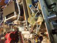
Is metal oxide. Does that mater? I'm also going to try and tidy up the wiring.
Looks like a rats nest.
What are your thoughts on the 10k resistor to ground after the output cap?
I took a look at my resistors. I have 24k and 39k. The 24k is metal film. The 39k
Is metal oxide. Does that mater? I'm also going to try and tidy up the wiring.
Looks like a rats nest.
Attachments
- Home
- Amplifiers
- Headphone Systems
- help with op amp headphone amp hum and distortion