Uhh .. erm .. No -- input bias is provided by the circuit in post #67.
The 100k will have too much offset at the AD817's rather high input current.
1N4002 should be fine subbing for the 1N4148. In fact, just about any forward-biased silicon junction will do.
The 100k will have too much offset at the AD817's rather high input current.
1N4002 should be fine subbing for the 1N4148. In fact, just about any forward-biased silicon junction will do.
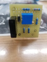
Looks good! Could've used an inexpensive (and lighter and much smaller) electrolytic, though.
Umm, no -- in this case we want to select a voltage from a range that remains fixed -- that doesn't expand and contract as the adjustment changes.
How'd you like the perfboard?
Umm, no -- in this case we want to select a voltage from a range that remains fixed -- that doesn't expand and contract as the adjustment changes.
How'd you like the perfboard?
Rick thank you for the response.
I found it a bit difficult. It's hard to get my mind away from the stripboatd mentality.
I should have some smaller electrolytics. I chose this one because it was a film cap with long leads. So i dont need to worry about replacing it down the road. Also the long leads would allow me to use the leads to connect directly the the main board ground.

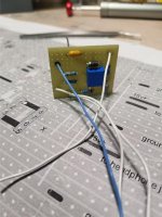
So now to figure out the logistics of mounting the small perfboard. This looks tricky. It's a tight area. Theres a few wires coming from around the opamps. I may have to reroute them so that the new perfboard sits nicely above oppamps.
I'll have yo figure out where on the veroboard I can put the input caps.
For the bypass resistor R2. Would it be ok to remove the old 10k and just substitute in a 470 ohm resistor?
I'll have yo figure out where on the veroboard I can put the input caps.
For the bypass resistor R2. Would it be ok to remove the old 10k and just substitute in a 470 ohm resistor?
Hey Rick,
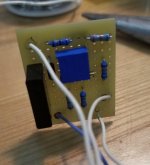
I decided to use a smaller ceramic cap for the circuit. The space where it needs to fit demands the use of a smaller cap. I've put in a bit of time and it looks like it should fit nicely. I'll take a pic once the perfboard is in position. What's the process for adjusting the trimpot.
I decided to use a smaller ceramic cap for the circuit. The space where it needs to fit demands the use of a smaller cap. I've put in a bit of time and it looks like it should fit nicely. I'll take a pic once the perfboard is in position. What's the process for adjusting the trimpot.
Attachments
Zero the output offset of each channel in turn.
Didn't we eventually have two trimpots -- once I stopped forgetting to draw the second one?
Didn't we eventually have two trimpots -- once I stopped forgetting to draw the second one?
OK, yes -- post 67 is the correct one.
Sorry. I forgot that the hypothesis was that the two AD817's would be close enough in input bias current requirements, that one adjustment would allow both outputs to get within a few millivolts.
Sorry. I forgot that the hypothesis was that the two AD817's would be close enough in input bias current requirements, that one adjustment would allow both outputs to get within a few millivolts.
Zero the output offset of each channel in turn.
Didn't we eventually have two trimpots -- once I stopped forgetting to draw the second one?
Do i put my leads on the outputs and set to measure dc?
Looks pretty good.
Yes. Unless the output coupling capacitor is already fitted. Then you'll have to measure at the op-amp end of the capacitor.
Once we see that it works as intended, may want to shorten the bias leads going to AD817's pin 3's -- they're fairly high impedance.
Also, I've forgotten whether it came up already -- the input leads may need to be shielded. But let's wait and see how much troublesome hum/noise there is. The AD817's rather high bias current is going to make some Johnson noise across 68k.
Cheers
edit: I'm going to have to bail for now .. and probably a couple days -- we're moving our youngest to her grad school over the holiday.
Last edited:
The question about subbing a 470r for the '10k bypass resistor' has me puzzled. I don't remember such a resistor, and I'm sorry but at the moment I don't have time to look back and sort it out.
If I can catch a bit of WiFi sometime before Wednesday 3Jun I'll do it.
Regards
If I can catch a bit of WiFi sometime before Wednesday 3Jun I'll do it.
Regards
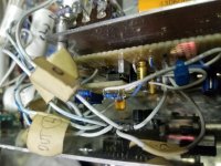
Hey Rick R2 in the first post is 10k. I've replaced with 470R.
You suggested to just tack on 470R ir 560R ontop.
I've also removed R3 100k as per your instructions.
I've added an input cap, It ended up being 22uf . You can see them, the gold color electrolytics.
I can use shielded wire for the inputs if needed.
You suggested to just tack on 470R ir 560R ontop.
I've also removed R3 100k as per your instructions.
I've added an input cap, It ended up being 22uf . You can see them, the gold color electrolytics.
I can use shielded wire for the inputs if needed.
Yaah, sorry -- I didn't organize that very well, eh !? 😱
Probably, start with the 4,7uF 50V input coupling capacitor. Be sure to take it from the MUSES volume control, not AFTER the 0,047uF coupling cap going to the valve grid.
Then lower the HPA gain: All you have to do is tack a 470 or 560R resistor across the 10k feedback resistor (R2 - pin 6 to pin 2). That'll cut the gain to a little over 3dBV, which is plenty since the AD817 can only drive a 32 ohm load to about 1,1Vrms.
At this point you should have a listenable HPA. There may still be hum, but it should be relatively in the background. And the distortion should be fixed.
And here's something else I forgot earlier -- a little protection for the volume control.
Regards
Here's the reference to the 470R
The question about subbing a 470r for the '10k bypass resistor' has me puzzled. I don't remember such a resistor, and I'm sorry but at the moment I don't have time to look back and sort it out.
If I can catch a bit of WiFi sometime before Wednesday 3Jun I'll do it.
Regards
Thanks for your help Rick. Looking forward to your input.
Sorry -- it took an extra day to complete the daughter's move. Then didn't get home 'til very late Thursday and am still recovering ..
It was the *bypass* that had me confused. As long as we're talking about the resistor that provides the feedback for the AD817, we're on the same page.
Still need two resistors to provide input bias -- the job of the 100k's. IIRC we fitted 68k's, which is uncomfortably high for a video op-amp. The hope is that we can get by with it: It's a handy value to help with the temperature drift; and choosing one appreciably lower will tend to load the source.
Cheers
- Home
- Amplifiers
- Headphone Systems
- help with op amp headphone amp hum and distortion