Is downshifting still continuing? What will be next TL072, LF351 and K2-W as final shot. 😀
I'm joking. 😛 🙂
I'm joking. 😛 🙂
I'm a newbie to opamps so unfortunately your humor is going right over my head.
Ideally I'd like to see if i can get this headphone amp working without scraping it and using a different design completely. My friend thinks the chips may be fried.
Ideally I'd like to see if i can get this headphone amp working without scraping it and using a different design completely. My friend thinks the chips may be fried.
Yes the drawbacks of the way of working keep haunting you. As suggested you need at least an input cap and I would use a slower opamp. If the opamps hum but amplify they are probably OK. The type you used by choosing randomly is not the most easy part to work with as it is a high speed opamp that requires careful design. In general the risk with fast parts and wiring is that they may oscillate and become a kind of transmitter. This also counts for tubes as you experienced already. Experience and reading datasheets beforehand can teach a lot in that aspect. A 50 MHz opamp with 350 V/µs slew rate might be a tad overkill for a HPA. In general: the slower a part is the more forgiving it can be when Veroboard and wiring are used.
I will repeat again: no sensitive circuit and no input wiring should be close to a mains transformer. If you can't move it you will have to shield it completely. If you would use a purpose designed and smaller PCB you could move it further away as that would be most optimal. You could split PSU and HPA if necessary.
I will repeat again: no sensitive circuit and no input wiring should be close to a mains transformer. If you can't move it you will have to shield it completely. If you would use a purpose designed and smaller PCB you could move it further away as that would be most optimal. You could split PSU and HPA if necessary.
Last edited:
I'm a newbie to opamps so unfortunately your humor is going right over my head.
Ideally I'd like to see if i can get this headphone amp working without scraping it and using a different design completely. My friend thinks the chips may be fried.
What's the source?.. And what headphones are you using?.. 🙂
As example: source soundcard with 2V RMS, and HP has 50 omh with sense 100-110 db, then you don't need OPamp, I guess current buffer will be enough. 🙂
p/s: or something like that...

JP,
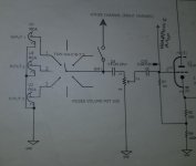
Thanks for the response. There's cap after the volume control. see the attached picture. I'll look into slower opamps. I'm gong to try using shielded cable at the inputs of the opamp. Also add some 220 ufd 50V non polarized on the output, with a 10K resistor to ground. If that doesn't work i can try some shielding as suggested. If that doesn't do it, I can separate the PS and HPA like you suggested. I hadn't even considered that option. Thank you for pointing out the possibility
Thanks for the response. There's cap after the volume control. see the attached picture. I'll look into slower opamps. I'm gong to try using shielded cable at the inputs of the opamp. Also add some 220 ufd 50V non polarized on the output, with a 10K resistor to ground. If that doesn't work i can try some shielding as suggested. If that doesn't do it, I can separate the PS and HPA like you suggested. I hadn't even considered that option. Thank you for pointing out the possibility
Attachments
What's the source?.. And what headphones are you using?.. 🙂
As example: source soundcard with 2V RMS, and HP has 50 omh with sense 100-110 db, then you don't need OPamp, I guess current buffer will be enough. 🙂
p/s: or something like that...
The HPA is in a tube preamp. It's the last thing to sort out before it's done. I have some Grado sr125s
I find the feedback resistor and decoupling capacitor values in Damon's schematic to be unreasonably high, but maybe I am missing something.
@Gregas: Maybe Linear Technology AN-47 by Jim Williams would be worth a read for you?
Thanks for the suggestion. I'll give it a look for sure.
JP,
Thanks for the response. There's cap after the volume control. see the attached picture. I'll look into slower opamps. I'm gong to try using shielded cable at the inputs of the opamp. Also add some 220 ufd 50V non polarized on the output, with a 10K resistor to ground. If that doesn't work i can try some shielding as suggested. If that doesn't do it, I can separate the PS and HPA like you suggested. I hadn't even considered that option. Thank you for pointing out the possibility
I won't calculate it (you can) but I think C10 is chosen too small when it couples both the tube circuit and the HPA. You do realize that both the tube circuit and the HPA will be regulated in signal both at the same time? So when using head phones at reasonable volume the tube circuit will also have input and thus output. Comes with the circuit of course. Also the HPA should be connected before C10 with its own coupling cap to avoid the DC offset of the tube circuit making things very difficult. When the values of the HPA circuit are what is written in the schematic a separate 1 µF 50V Wima film cap in 5 mm pitch per channel will work OK. * there is no input filter at the inputs so after the source selector. I thought you changed that?
edit: couldn't resist and C10 is indeed way too small when used for both but there is a huge error in the circuit anyway so please correct. The preamp can not function good as it is built now as it will lack bass because of the 100 kOhm load of the HPA...
When will you start to design, plan and calculate circuits? I suggest to start NOW. Aujourd'hui, immédiatement, toute suite!
Last edited:
The hum would need to be almost inaudible before shielding the HPA inputs would help.
You have 4 problems, and a couple ancillary issues:
- the schematic in post 25 shows the HPA signal coming from the grid of the first tube stage; since it's a self-biased Cathode-follower, that gives the HPA a huge DC offset! -- give it its own input coupling capacitor (again, j-p advised), and take it from the MUSES volume control wiper (before C10) -- it'll need to be a lot larger than the 0,047uF for the tube Grid, say 4,7uF or 10uF @10 to 25V -- don't be afraid of electrolytics, especially for a test to confirm that it works
- 20dBV is too much gain -- by about 17dBV! The 32 ohm Grado HPs will demand the AD817's full 50mAp-p at ~1,13Vrms (~40mW), which is already in the range of typical input sources. You won't like the sound if the op-amp hits its current-limit. Lower the feedback resistor (if I get it done within the edit-time-limit, I'll type in the component designation; Alrighty Then: R2) to 30 - 50% of the op-amp's '-'_to_ground resistor.
- the AD817 is not a good choice for this service; we can probably find a way to make it work, but you'll know a lot more electronics by then, than you do now 😉
- the rectifiers around the LM7x15 regulators show a 1N4742A, which is a zener -- change to 1N400x; otherwise high frequency, high amplitude crap on the power line can go right around to the regulated supply
-- It looks like you might have a Star Ground wire passing through the center tap of the 187Axx transformer. That's a no-no. The relatively high-current pulses charging the 1000uF caps will corrupt that line.
-- Move the bridge and 1st filter caps to the transformer (IIRC jean-paul mentioned this). Right now you have almost 40Vp-p going the whole length of that braided feed. Braiding is great for reducing radiated EMI, but doesn't help a whit to reduce what gets coupled capacitively. The included pic suggests moving the whole supply -- which would be nominally better. But you could start with just the bridge and first filter caps and solve the bulk of the problem. If you do take the regulators, remember to take their output capacitors, too -- they're needed for stability.
As a general rule, power supply sections are best kept sequestered in a distant corner of the chassis whenever possible. Try to make a habit of that in future projects. 😉
-- There are some scary places in the point-to-point wiring. Try to include what they call a Service Loop in each part -- enough slack to allow reconnecting it, if for some reason you needed to just cut the wire to disconnect the part.
You have some really nice metalwork there -- I'm jealous.
Cheers
edit: Sorry for duplicating some of j-p's work. It takes me so-o-o long to complete one of these .. 😱
Attachments
Last edited:
Ha ha it is becoming a repeating cycle isn't it? 🙂 Same with way too high gain, it is liked by many that have the "just doing something" way of working 😀
Since it starts to annoy me and I think I have done enough usefull suggestions that solved issues I bail out. Gregas, have fun and please think of doing things a more efficient way the next device.
Since it starts to annoy me and I think I have done enough usefull suggestions that solved issues I bail out. Gregas, have fun and please think of doing things a more efficient way the next device.
Last edited:
Thanks for the suggestion. I'll give it a look for sure.
Stop vandalizing it - enough, please. 🙄

What do you even mean by that in the given context? Maybe you should stop vandalising the thread with nonsense...!? Or do you have another high-speed video OpAmp to recommend to a DIYer using perfboard?
JP thanks for your help. You helped to start the ball rolling.
In the future I'll post before I build. thanks
Rick,
there's a lot to digest there. let me read it over and figure out exactly what your suggesting. Thanks!
In the future I'll post before I build. thanks
Rick,
there's a lot to digest there. let me read it over and figure out exactly what your suggesting. Thanks!
Yaah, sorry -- I didn't organize that very well, eh !? 😱
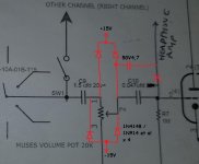
Probably, start with the 4,7uF 50V input coupling capacitor. Be sure to take it from the MUSES volume control, not AFTER the 0,047uF coupling cap going to the valve grid.
Then lower the HPA gain: All you have to do is tack a 470 or 560R resistor across the 10k feedback resistor (R2 - pin 6 to pin 2). That'll cut the gain to a little over 3dBV, which is plenty since the AD817 can only drive a 32 ohm load to about 1,1Vrms.
At this point you should have a listenable HPA. There may still be hum, but it should be relatively in the background. And the distortion should be fixed.
And here's something else I forgot earlier -- a little protection for the volume control.
Regards
Attachments
Hey Rick,
Good stuff. I was thinking, I don't really need to stick with those AD817 chips. Especially if they are not ideal.
How did you calculate for the 4.7uf electrolytics?
Good stuff. I was thinking, I don't really need to stick with those AD817 chips. Especially if they are not ideal.
How did you calculate for the 4.7uf electrolytics?
Didn't calculate -- that's just a typical value for coupling 10k to 25k inputs. (Am guessing that we might lower that 100k at some point since the AD817's 3,3 to 10uA input current spec will produce a 0,33V to 1V offset.)
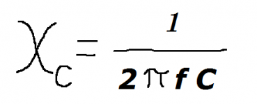
The formula for capacitive reactance is:
(couldn't figure out how to get the image to live here .. 😱 )
Where f is frequency in Hertz, and C is capacitance in Farads ..
but it doesn't add/compare directly -- you have to borrow some of Pythagoras' work to account for the 90° phase difference.
Cheers
The formula for capacitive reactance is:
(couldn't figure out how to get the image to live here .. 😱 )
Where f is frequency in Hertz, and C is capacitance in Farads ..
but it doesn't add/compare directly -- you have to borrow some of Pythagoras' work to account for the 90° phase difference.
Cheers
Attachments
> How did you calculate
Don't calculate. Remember a few handy values and extrapolate.
For 17Hz:
1KOhm needs 10uFd
So:
10KOhm needs 1uFd
100KOhm needs 0.1uFd
10 Ohm needs 1000uFd
Rick's 5uFd for 10k-25k is generous, <4Hz @ -3dB, but at electrolytic prices that is not wrong. (In fact e-cap distortion reduces as you oversize, so even 22uFd or 47uFd may be warranted in studio work.)
Just woke up and see this. Don't teach someone that already works in a plain wrong way not to calculate coupling caps. It will not lead to better results for sure as working on auto pilot and "just doing something" never does. The proof being this thread and the tube preamp thread. Also teach to use the correct capitals and unit names.
It is kOhm, µF, mV, MV (Megavolt), kA. So 100 kOhm, 4.7 µF etc.
The circuit needs 1 µF to 4.7 µF so a 5 mm film cap is best choice, better than electrolytic caps certainly in a tube device with hotter temperatures.
This online tool does calculate and shows all results:
RC Low-pass Filter Design Tool
Last edited:
> Don't teach someone that already works in a plain wrong way not to calculate coupling caps.
I thought you bailed:
I thought you bailed:
...Since it starts to annoy me and I think I have done enough usefull suggestions that solved issues I bail out..
- Home
- Amplifiers
- Headphone Systems
- help with op amp headphone amp hum and distortion