What wasn't solved was the low volume and the under powered sound. But while I was looking on the internet I had my headphones on and the device on full gain and full volume which was still nothing near very loud sound levels. After a few minutes the sound became louder and eventually I had to turn down the volume to not let it hurt my hears. After some more minutes I could turn down the gain switches one step and had my old volume levels back..
Does it always happen when you power on the amp. or was it a singular phenomenon?
I ran a quick simulation now.
I'm the first to admit that I'm less than an expert on designing audio or using LTSpice.
For example I used two resistors as a "simulated" pot...
Thanks. Don´t be too modest, the circuit looks good to me. Using two resistors instead of a pot. is absolutely right (a pot. is nothing more than a voltage divider).
Thanks. Don´t be too modest, the circuit looks good to me. Using two resistors instead of a pot. is absolutely right (a pot. is nothing more than a voltage divider).
Well, I'm not educated and have used LTSpice less than a year.
And tbh, I sometimes feel the DIY community could use a bit more modesty.
Thanks for the compliment 🙂
I have now ready a breadboard setup of the Lehmann circuit (a variant of the so called diamond buffer when I´m not wrong), without the opamp gain stage. It´s really tricky to get very low DC offset voltage at the output.
So I would like to ask you what will be the criteria for transistor matching. Should I match it for hfe, Vbe/Ib or something else?
So I would like to ask you what will be the criteria for transistor matching. Should I match it for hfe, Vbe/Ib or something else?
It´s really tricky to get very low DC offset voltage at the output.
So I would like to ask you what will be the criteria for transistor matching. Should I match it for hfe, Vbe/Ib or something else?
Vbe first, hfe second.
Also very important is resistor matching.
Thank you for the quick reply. I also figured out that resistor matching is important (maybe more than transistor matching). Also the symmetry of the supply voltages will influence DC offset, I was able to trim out DC near zero by variation of pos. (or neg.) supply voltage (about 100mV will give 1mV offset change). But this is not the proper way to get low offset, I guess.
what about measurements? Particularly S/N ratio..
Also can you get DC offset down to 3mv or less?
Also can you get DC offset down to 3mv or less?
what about measurements? Particularly S/N ratio..
Also can you get DC offset down to 3mv or less?
I struggled many hours at the weekend, attempting to get low offset.
Transistor matching isn´t that easy like it seems, especially Vbe (hfe is not a big problem). Transistor testers measures Vbe at a fixed base current (Ib), mine measures at Ib=5mA and collector open (but Vbe depends on Vce). This is far far away from the quiescent point in the application, so I found it useless to do it this way. The next step was to build up a test circuit to measure Vbe with the same conditions (Ib,Vce) as in the application, but unfortunately Vbe highly depends on temperature and the collector current is warming up the transistor very quickly. So I was not able to measure the transistors at the same temperature. Now I´m clueless regarding a correct measurement.
Some more results of my experiments:
At first I matched the resistors <0,1% with a LCR meter and the supply voltages symmetry within 10mV. The goal was to bring into focus only the transistors.
Next I selected 20 pairs of complementary transistors only by chance, both BD139/140 and BC550/560 for DC offset measurements. The measurement results surprised me.
It measures from 1mV to (and that was the surprise) max. 6mV. I could not get higher DC offset than this 6mV, no matter which transistors I combined.
My conclusion (for the moment): Don´t worry to much about transistor matching in this circuit
Another issue is the thermal drift of the offset voltage. I was able to change it several mVs just by touching one transistor with my fingers. The ultimate test was the removal of one heatsink ( the other transistor still on the heatsink). Wow, DC offset increased to over 50mV (within a minute or so), I stopped it because I wouldn´t burn the transistor.
So, it might be a good thing to have thermal coupling in between the complementary transistors.
Well, I´d like to add that 6mV (in the worst case) is not perfect, but it causes no headaches to me. My orig. Lehmann measures 5mV at one channel, so I´m in good company.
Hey,
I've been playing around with the Lehman a bit. Placed back the original resistor values but upgraded them to RA resistors instead of the blue DALES.. Can't say it makes much of a difference.
What does make a big difference are the PSU output caps. These caps are influencing the sound even more than the electrolytes at the opamp.
I've played around with several sets and found out that they are very sensitive when pairing with different opamps.
I had the Nippon LXY 560uf 35V caps in place and found that the OPA2604 (or dual OPA604s) sounded good but veiled in some kind of way. I decided to roll my OPA627s and this created a more clear sound but on the thin side.
So I remembered from the build up and experimenting with different sets of psu output caps that these could influence the sound quite a lot. For example the LXY 560uf 35V sounded more 'full' and lesh harsh than the LXY 470uf 35V and the Panasonic FRs sounded to thin but more detailed. But at the time I used one opamp to keep the device constant.
I have bought myself some 680uf 25V Panasonic FMs and 680uf 25V Panasonic FRs and tried different sets with different opamps and this were really day and night difference. switching caps mad me want to switch opamps really quickly. I've been using OPA627s and OPA2604 for the comparisson.
I've learned that different caps especially sound different in poor designed circuits.. Well it's not a secret that the PSU of the Lehmann is not of world class and quite simple.
Right now I'm cruising on Panasonic FM 680uf 25V as my output caps. The 680uf FRs give a bit more clarity but are also thinner and more tiring.
Attachments
Last edited:
I've learned that different caps especially sound different in poor designed circuits.. Well it's not a secret that the PSU of the Lehmann is not of world class and quite simple.
LM317/337 (designed in the 1970s) is not the worst choice, especially with bypass cap (10µ-100µ) at the adj. pin, ripple rejection and noise performance are fairly good. But you are right, it´s not a "high end" solution.
Local decoupling is an important issue (as you already stated) and it´s nice to play around with different caps. So you ended up with the Pana FM as the best choice?
I´m interested in the zener-diode modification of the LM317/337 and would like to ask you:
-which zener diodes do you use?
-the output voltage calculate from Vz+1,25V(Vref), is this correct?
-what voltages do you meassure at LM317/337 ouputs?
Thanks in advance
My kit arrived last week; resistors 1% (Philips), all capacitors checked and probably are original, PCB quality correct... OK, good points, but the silicone is bad: 560/550 with very low values and Toshibas aren´t "Y" spec (well, I assumed that it was fake and I will change this).
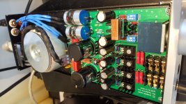
Well, I replaced some components like resistors for Vishay/Koa/Xicon, caps (Mundorf Mlytic, MCap, Nichicon Muse and KW, Ero/Roederstein... ) and I have mached 550/560 and BD139/140 transistors.
Now I have some questions and I need your help and experience please;
. Any recommendations for 100p caps? I have a pair of BC/130p but I don´t sure if it´s a good selection.
. I want to use the Zener mod. but I don´t like the tantalum caps. Recommendations?.
. Last question, I want to use two OPA627 (dual/mono) but someone has used class A Bias with this configuration?
Thanks
Last edited:
Which pcb version is the best to order from the ones available on ebay? Is the ground plane for power rails split or single on it?
. Any recommendations for 100p caps? I have a pair of BC/130p but I don´t sure if it´s a good selection.
These RF input filter caps are not that critical, you can use any ceramics or if you dont´t like them, use film foil such as Wima FKP2. You can use 130p instead of 100p, no problem it will work fine.
Use low ESR electrolytics, it could be fiddling to fit them on the PCB because there is not a lot of space in these positions.. I want to use the Zener mod. but I don´t like the tantalum caps. Recommendations?.
I´m not sure what you mean.. Last question, I want to use two OPA627 (dual/mono) but someone has used class A Bias with this configuration?
Which pcb version is the best to order from the ones available on ebay? Is the ground plane for power rails split or single on it?
If you only want do a simple amp, this kit is right. The problem is when you want do an "up grade". A single a pcb is the best option here because you don´t use some kit components probably as my case.
I'm not sure about your last question. The PCB has two layer and the upper side is the ground plane.
Andreas, thanks for your comments. 🙂 My last question is about this Class A Bias MOD.
I have a adaptator from two chanel OPA like a OPA2134 to two mono OPAs (I want to use a pair of OPA627). Is it possible to make the Class A Bias MOD with two OPA627? Someone has done it?
Thanks
Of course, you can use 2 OPA627 with single/dual adapter. I can´t figure out what the guy in the link you posted is doing, so be careful about that.
I would suggest to complete the amp. without this mod.
To a later time you can try this out (but make the function of this mod. clear to yourself, don´t just imitate it "blind").
I would suggest to complete the amp. without this mod.
To a later time you can try this out (but make the function of this mod. clear to yourself, don´t just imitate it "blind").
Thanks Andreas.
Yes, you are right. I´m sure that is a better idea check this mod with a cheap OPA and when my amp is finished.
Other link with the same MOD Matrix M-Stage ReviewHeadfonia Headphone Reviews
I´m not sure but I think that I readed something on Headfi... 😕😕😕
Yes, you are right. I´m sure that is a better idea check this mod with a cheap OPA and when my amp is finished.
Other link with the same MOD Matrix M-Stage ReviewHeadfonia Headphone Reviews
I´m not sure but I think that I readed something on Headfi... 😕😕😕

hello i am building Lehman clone and i want it will match to original lehman linear se or superpass it. i have clean board and few parts ordered. i gather some help and this is waht i am gather until now. i know basic soldering. help me to complete the parts that i need.
this is the parts that i ordred so far
tell me if it is ok and everything match.
here is the parts that i need but i dont know which parts to order i want quality ones.
i need excat brands with the proper vdc and uf/PF stats.
i just marked what i need
parts from hificollective will be granted they have quality parts.
also from digikey/farnell/rs components etc..
i put PRP 9372 IN circle but i understand there are 0.5/1W in diffrent and R types and i dont which to place so i justm arked it as well.
i dont understand in electronics so please in the markings just place the part that i need
thnx for all help.
this is the parts that i ordred so far
tell me if it is ok and everything match.
An externally hosted image should be here but it was not working when we last tested it.
here is the parts that i need but i dont know which parts to order i want quality ones.
i need excat brands with the proper vdc and uf/PF stats.
i just marked what i need
An externally hosted image should be here but it was not working when we last tested it.
parts from hificollective will be granted they have quality parts.
also from digikey/farnell/rs components etc..
i put PRP 9372 IN circle but i understand there are 0.5/1W in diffrent and R types and i dont which to place so i justm arked it as well.
i dont understand in electronics so please in the markings just place the part that i need
thnx for all help.
- Home
- Amplifiers
- Headphone Systems
- [Headamp] upgrading a Lehmann BCL clone