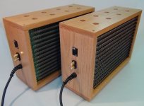
Since the H2 is basically a green board, I decided to mount it in a build box hardwiring the DC wall wart and upgrading the RCA connectors. To trick it out, I decided to have one of these meters
<https://www.amazon.com/bayite-Voltmeter-Motorcycle-Polarity-Protection/dp/B00YALV0NG/ref=pd_bxgy_328_2/135-4401197-3086004?_encoding=UTF8&pd_rd_i=B00YALV0NG&pd_rd_r=db81c8fe-91fd-11e9-a2fd-f53af8016d18&pd_rd_w=JiIv8&pd_rd_wg=PmLbm&pf_rd_p=a2006322-0bc0-4db9-a08e-d168c18ce6f0&pf_rd_r=1AEGB56KVWF87502299J&psc=1&refRID=1AEGB56KVWF87502299J>
which supposedly display 0-30V DC...and they do, 0.00V lights up for both the nominal 16V H2 power supply as well as a 9V battery. :-(
What am I missing? Is the amperage from both the H2 and battery too low to trigger the display?
Thanks!
Configure your digital multimeter (test equipment) to display milliamps, and splice it in temporarily. I think you'll find that your H2 board draws somewhere between 30mA and 60mA. Then check whether your Amazon-device plus the circuit board you built to drive it, gets the right answer with 30mA flowing.
Appreciate the thought on measuring the milliamp output of the H2. Did measure the voltage but not the current.
My problem was that I did not realize that Red and White leads needed to be connected together for V+ connection. All good now.
Thanks
My problem was that I did not realize that Red and White leads needed to be connected together for V+ connection. All good now.
Thanks
Mr. Pass, if you wanted an overall sound with some H2 in it how would you portion it, between the preamp and the power amp? H2 in the pre and very little in the power or vice versa, or a little in both?
Thanks. nash
Thanks. nash
My favorite place for it is in the output stage of the amplifier.
Just my personal opinion, though - love those output stages......

Just my personal opinion, though - love those output stages......
Hypothetically imagine a push pull output stage whose pullup half has a gain of "G" volts per volt, and whose pulldown half has a gain of 1.5x"G" volts per volt.
My favorite place for it is in the output stage of the amplifier.
Just my personal opinion, though - love those output stages......
Just so that I understand, you do mean output stage of the power amplifier? I had posted the query since I have made your BA3 pre and F5TV3 power amps and they both have P3 to allow H2 adjustment, but of course they both have it in the first stage. Just trying to better understand how to voice the overall system that has pre and power amps.
Thanks. nash
Ok....to make some "un-symmetry" in a PP stage to get H2?Hypothetically imagine a push pull output stage whose pullup half has a gain of "G" volts per volt, and whose pulldown half has a gain of 1.5x"G" volts per volt.
The output stage in e.g. M2(X) is made as symmetrical as possible to cancel out H2? which FW PP has H2 dominans? ….will see if I can find one...
Any mismatch between the positive and negative halves of an output stage will
generate 2nd harmonic. Usually we make efforts to make them symmetric so
as to minimize this.
generate 2nd harmonic. Usually we make efforts to make them symmetric so
as to minimize this.


Would it be possible to make a PP output stage using the same device like IRFP240 for both push and pull and use the same technique as in the "tube world" where a phase splitter is used? …..if the two IRFP240 was matched then H2 would be almost gone? …..would that require an output transformer?
ever heard of F6?
of course , you can take a look at Quad 303 too , and numerous amps from Yore
of course , you can take a look at Quad 303 too , and numerous amps from Yore
I just looked at F6......so Papa also like output stages that generates very small amount of H2?
In F6 build thread I can probably find full schematic of F6 to see how it is made in details.
Many years ago I built some Quad 405 clones…..so maybe I had such kind of amp. Still have the schematics somewhere…….
In F6 build thread I can probably find full schematic of F6 to see how it is made in details.
Many years ago I built some Quad 405 clones…..so maybe I had such kind of amp. Still have the schematics somewhere…….
I appreciate all sorts of performance characteristics.
If you look at FW amplifiers, you will see that each is unique in some way.
If you look at FW amplifiers, you will see that each is unique in some way.
So "discontinued" does not mean that now you have developed something better in performance.....just different? …..I know if depends very much of which kind of speakers......and "ears".
What is your favorite amp for the big horns you have?
What is your favorite amp for the big horns you have?
I have to understand JFET characteristics better before making such an amp. But maybe we could use J113 for it.....they are cheap in large numbers.
Some JFET curves looks like there is a linear relation between Vgs and Id and other curves shows the "square law" so distance between Vgs curves gets larger with raising Vgs. I have not yet understood what makes the difference......
Some JFET curves looks like there is a linear relation between Vgs and Id and other curves shows the "square law" so distance between Vgs curves gets larger with raising Vgs. I have not yet understood what makes the difference......