Hello,
C1 and C2 are in the correct places on the PCB.
My Preference is also a regulated power supply. I have built more than a few.
My understanding of the switching power supply filter in the store is that it is designed to remove high frequency switching noise, you know above 20K kind of stuff.
This TriAd switching 12Volt DC wall wart produces a lot of switching noise in the below 22K audio frequency range.
See the attached screen shot of noise voltage, O'Scope and FFT for between 20 and 20K.
Thanks DT
Since the H2 V2 board only requires +12V DC, you can start with a +24V wall wart and "spend" those extra 12 volts to get Massive Overkill Ridiculously Excessive Filtering And Regulation. Who knows, it might even improve the sound a little too.
For example, you could first knock down the SMPS high frequency noise with a pair of (the diyAudio Store SMPS filter kits) connected in series. The output of the second board is more than 23V DC because each of those filters have a very low in-to-out resistance, less than 0.2 ohms each. Next comes an 18V DC voltage regulator, either MC7818, or LM317, or LTC regulator, or other options. Finally, last in the chain, is a Jung/Didden Super Regulator set to +12VDC. You'll have vanishingly low noise on your +12V power supply, from 60 Hz to 60 kHz. No spikes in the frequency response.
BTW the Store SMPS filter's rolloff corner happens to be down around 2-3 kHz. Attenuation of noise begins at 2-3 kHz. That's how you get tons of attenuation at 50 kHz: you roll off early and you roll off steeply. At least that's what I was thinking when I designed the board they sell in the Store. Click on the link in the Store's sales blurb, it'll take you to the Forum where I explain the board.

Playing with the H2 V2 is fun. I am some what impressed at the positive and minus phase of the distortion and amount of H3 also present. I may come back around and do some critical listening with the H2 V2, a non-distorting headphone amplifier. I am done with this for a while. Perhaps next I will try a circuit with a J113 current source to see what/if there are any PSRR changes.
At this point messing around with wall warts, filters and regulators is way too much fun.
By putting the battery in the shielded steel junction box with the H2 V2 I did get the 20 to 22k noise down to 3.4 uVrms average.
Thanks DT
At this point messing around with wall warts, filters and regulators is way too much fun.
By putting the battery in the shielded steel junction box with the H2 V2 I did get the 20 to 22k noise down to 3.4 uVrms average.
Thanks DT
@ cubicincher
Dirk, I have to ask if the labeling on your front and back plates is CNC/engraved, labels, stamped, stenciled, or other. Great looks with the process used.
MM
Dirk, I have to ask if the labeling on your front and back plates is CNC/engraved, labels, stamped, stenciled, or other. Great looks with the process used.
MM
Hello Kokanee,
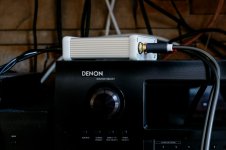
the labeling is CNC engraved (without colour - which is also possible). Black anodized aluminum engraved.
Made by Schaeffer AG, Berlin. You can download their CAD-software (Front Panel Designer) for free to design your own front-/backplates.
Their US-subsidiary is Front Panel Express.
Cheers
Dirk 😉
the labeling is CNC engraved (without colour - which is also possible). Black anodized aluminum engraved.
Made by Schaeffer AG, Berlin. You can download their CAD-software (Front Panel Designer) for free to design your own front-/backplates.
Their US-subsidiary is Front Panel Express.
Cheers
Dirk 😉
Hello, guys!
What a project! 😊
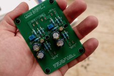
As always I've went with my own PCB design to have a little more fun. There were about 20-30 of J113 on hands so mannaged to chose a pair in around 2.1 Vp. I my case I've chaned R6 to 50R and P1 to 100R (or you can leave P1 at 50R and increase R6 to 50R-100R) to get desireble level of H2.
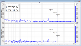
I tried to set it up as accurately as possible and it turned out pretty damn good! On last picture you'lle see measurements at 0.5 Vrms output into 47k load after 30-40 minutes runtime. And we have about -40 dB H2, -62 dB H2 and -82 dB H3 and THD+N is 1.06% at both channels. There is unexpected spike between 1k and 2k but it seems I can live with it.
As always, thanks for Mr. Nelson for such fun, simple and handy project! 😍
What a project! 😊
As always I've went with my own PCB design to have a little more fun. There were about 20-30 of J113 on hands so mannaged to chose a pair in around 2.1 Vp. I my case I've chaned R6 to 50R and P1 to 100R (or you can leave P1 at 50R and increase R6 to 50R-100R) to get desireble level of H2.
I tried to set it up as accurately as possible and it turned out pretty damn good! On last picture you'lle see measurements at 0.5 Vrms output into 47k load after 30-40 minutes runtime. And we have about -40 dB H2, -62 dB H2 and -82 dB H3 and THD+N is 1.06% at both channels. There is unexpected spike between 1k and 2k but it seems I can live with it.
As always, thanks for Mr. Nelson for such fun, simple and handy project! 😍
Attachments


Very nice @onemorecap
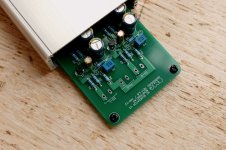
Well i did my own pcb, looking at the layout mr. Pass allready did so well.
I like the typical "Pass" GND connection surrounding the borders of the pcb, just like in the old day's (BoSoZ etc...) great Nelson, thank's...
I only soldered 1/2 of the pcb, to test it for now.
When pcb is done and shielded into some box, i will be using it to compare "real THD" vs. DSP generated THD 😵
Okay nevermind that for now.
The psu is an old LG psu, and the voltage is steady 12vdc, also when loaded.
I set the gain to near zero (R1=22K, R2=10K), and the circuit are giving 1.1v out, when feeded with 1.0v from Victors 1KHz oscilator, inverting as it should.
The J113 i have are a set of (which i tested in a little rig.) 2.228vdc/27.6mA & 2.230vdc/27.5 or so.
The P1 is 100ohm, and R6 is stock 33ohm
When setting T2 at 1.026vdc, the 2.harmonic is ~1%, and everything is looking good i guess.
Considering the pcb is in the open on my noisy desk, i think the FFT are looking pretty good.
Jesper.
In post 62 quoted above, Nelson Pass notes the voltage at the J113 drain (=T1) settles at 4.40-4.60V.In the adjusted circuit the jfet settles into a Drain voltage between
4.40V and 4.60V at about 27 mA.
I've just built a H2 V2 board from DiyAudio, and for R3 (221Ω), I used paralleled 690Ω and 330Ω resistors (nominally 223Ω) as that was the closest a match I could get for 221Ω and I was, well, impatient. One paralleled pair measured before installation was 223, the other 221.
The bag from DiyAudio had my J133s marked as 10.5V. I have the circuit running now, and with the in/outs unconnected and allowed 10 min setting time, adjusted P1 to get 10.51V for both channels. I decided to check the voltage at T1 (its on the other side of R3, and connected the the J113 drain), and I measure 4.38V for one, and 4.60V for the other. I'm guessing this difference is due to the ~2Ω difference in what I used for the R3s.
My question is if I should adjust the P1s to get these values at T1 equal to each other, say at 4.50V, and not worry about creating a small mismatch at T2? It seems to me I should (I don't see any consequences in this simple circuit as the voltage at T2 doesn't have any job except to drop across R3 and set the J113 drain at a nominal 4.50V), but felt it is best to ask those who know a lot more than me.
The calibration of the bias points of the jfets is nominal, based on the matching to .1v pinch off voltage. Usually this gets you pretty close, but it's not perfect. Your resistance is not at fault, rather you are at the edge of the accuracy of the process.
In the end, real accuracy comes from having a distortion analyzer to match the channels, but I suggest you relax and listen to it -precision is not what this circuit is about...

In the end, real accuracy comes from having a distortion analyzer to match the channels, but I suggest you relax and listen to it -precision is not what this circuit is about...
Many thanks for your advice (including about relaxing 🙂), and for your generosity in sharing this circuit will all of us.
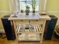
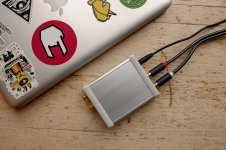
I have it hooked up within an old DVD chassis that I recycled for an enclosure, using its power supply, RCA jacks, etc. So far, it is a subtle and pleasant effect, and I look forward to exploring more music with it.
I have it hooked up within an old DVD chassis that I recycled for an enclosure, using its power supply, RCA jacks, etc. So far, it is a subtle and pleasant effect, and I look forward to exploring more music with it.
Hi all...
I finally got the H2 generator boxed up, and did some screenshots, to compare how important shielding is 😊
See post #308 for how it look's without shielding.
I took the FFT with showing mV as the paper's tell that the H2 number's are at 0.5v out.
The H2 is as Nelson describe raising with raised input/output voltage.
I will as i proberly allready wrote, use this generator to compare between DSP generated H2, my Tube 300B-SE and this H2-Gen.
I'am really slow right now, as summer is comming here in DK, but promise to come back with some result's sooner or later here.
Jesper.
I have a second H2V2 project in mind and could use some advice.
I intend to build a stand-alone unit in its own case, but I would like to incorporate a bypass switch. What type of switch would be recommended? Would it be possible to use the switch when the system is live?
Thanks in advance for entertaining my rudimentary questions.
I intend to build a stand-alone unit in its own case, but I would like to incorporate a bypass switch. What type of switch would be recommended? Would it be possible to use the switch when the system is live?
Thanks in advance for entertaining my rudimentary questions.
I also have a second H2 build (as a preamp this time) in mind. A bypass switch is an interesting thought and I am interested to see what is recommended here with regards to switches, since I have a bad experience with a Lorlin rotary switch in my current preamp for selecting input sources. I also need to select between two input sources for the H2. Thinking to use a good old 3 pole toggle switch for source selecting, rather than a rotary switch.
While a bypass switch is a great idea or feature, I don’t think switching while the system is alive (playing music) is a great idea. The circuit is phase inverting and bypassing the circuit will have opposite phase to the speakers. I.e. you would not be able to A/B compare the H2 effect vs no H2 by simply switching to bypass while playing music. At least, that is my understanding.
While a bypass switch is a great idea or feature, I don’t think switching while the system is alive (playing music) is a great idea. The circuit is phase inverting and bypassing the circuit will have opposite phase to the speakers. I.e. you would not be able to A/B compare the H2 effect vs no H2 by simply switching to bypass while playing music. At least, that is my understanding.
While thinking about a second H2 build - has anybody done some cap (C1, 10uF) rolling with film caps or different values for better results?
I intend to build a stand-alone unit in its own case, but I would like to incorporate a bypass switch. What type of switch would be recommended? Would it be possible to use the switch when the system is live?
I have a H2 V2 in its own case hooked up in the processor loop (located before the preamp) of a Luxman R-113 receiver. I can switch it in and out at will (bypassing takes place within the R-113). Because the H2 V2 remains powered at all times, there is no thump. So what you want to do should be doable, but as suggested by twocents, my particular switching arrangement does not change phase; it remains as you configure it, one way or the other.
More generally, bypassing the H2 should be achievable by a DPDT switch, with the On position connecting the incoming signal to the H2 inputs and the Bypass position connecting the incoming signal to the H2 outputs. Only the hot signal wires need to be switched; the signal grounds can be left alone.
As for phase, if the speakers downstream are set up in an inverted phase configuration for when the H2 when engaged (Pass’s write up indicates to not invert phase before the H2), it is tempting to consider wiring the DPDT switch to invert phase for the bypass position, so phase will be correct when it reaches the speakers. However, I don’t know if the same reasons for not inverting phase prior to the H2 also apply to a preamp or amp. I inverted at the speaker terminals.


I am pretty sure, that Peppennino is feeling better - after his 'trip' into the depth of H2...
😵
Enjoy the sound!
Dirk
😵
Enjoy the sound!
Dirk
- Home
- Amplifiers
- Pass Labs
- H2 V2 BUILD