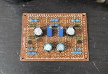

Finally got some time to build the H2 where Nelson provided board and FETs. Thanks Nelson. Gave me a chance to try out my new toy, QuantAsylum QA403 Audio Analyzer. Looks good, with a 1db difference in the 2nd harmonic. Looks just like the picture in Nelson's writeup.

Would you mind to show the back side too? Just out of curiosity!99% not yet test
Interesting. It looks quite the same of what I posted in #210.
Would you mind showing where is the noise floor with the QA403? I guess well below -110dB, right?
I don't have the full setup with the H2 handy, but this is a loopback test I had done earlier.
H2 Update!
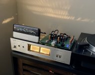
To satisfy my curiosity, I put a separate 12VDC SMPS in my amp with the H2 (https://www.diyaudio.com/community/threads/h2-v2-build.376337/post-6955224) to see if that would clear the turn off thump. I’m happy to report that it does! 😎 It’s also virtually silent. The mains hum is inaudible unless I turn the ACP+ volume WAY up (beyond any level at which I would ever listen) and pause playback.
Back in the main rig it goes for a rotation. Again, I’m very happy with this experiment. It sounds very good.
I can live with two mains plugs at the back for now. 😊
Attachments
I think it is a good idea to know these formulas.
Hang this on your wall for reference.
https://www.amazon.com/Electronics-...r=3M9GEQFGW9ZG25NH2XR2&qid=1649620387&sr=8-16
I think it is a good idea to know these formulas.
Put this poster up on your wall.
https://www.amazon.com/Electronics-...r=3M9GEQFGW9ZG25NH2XR2&qid=1649620387&sr=8-16
This is a distortion factory.
1 volt into 10K ohms
12 Volt Gel cell power
No box or shielding open on bench top
0.72% THD+N
11.120 Gain
Thanks DT

1 volt into 10K ohms
12 Volt Gel cell power
No box or shielding open on bench top
0.72% THD+N
11.120 Gain
Thanks DT
Take the Drain voltage down a little bit and you should be able to get a 10 dB spread of H2/H3...

I am waiting for the trim pots to arrive from Digikey. Mouser is much faster to my place but they are out of stock.Take the Drain voltage down a little bit and you should be able to get a 10 dB spread of H2/H3...
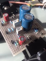
This is test #2 with a 10R resistor soldered on the back of the PCB in place of the wire jumper in test one.
The FFT does look different with the 10R resistor jumpered on the back in place of the trim pot. The H2 distortion is now down 25dB ish from the previous test.
Rather than damaging the PCB I will wait for the trim pots to arrive from Digikey to dial in the desired distortion profile.
This H2 V2 PCB is very sensitive to noise on my bench. I now have it in a 8X8X4 electrical J-Box bonded to the ground on the APx555.
Thanks DT
Last edited:
I am thinking most people who either made or plan to make this will be using it in the home stereo system.
I was wondering (and I apologize if it has been covered) but could this be housed in a little box with some RCA'S, so it could go in between a car audio DSP and the speakers amp? Since the 12 volts and ground will be back in the area, the little box would go that would be covered. Then to top it off, could blue tooth be wired in and have a transmitter at the front of the car to change how much H2 is being supplied? Just wondering.
I was wondering (and I apologize if it has been covered) but could this be housed in a little box with some RCA'S, so it could go in between a car audio DSP and the speakers amp? Since the 12 volts and ground will be back in the area, the little box would go that would be covered. Then to top it off, could blue tooth be wired in and have a transmitter at the front of the car to change how much H2 is being supplied? Just wondering.
Last edited:
Hello All,
This is fun playing with JFET distortion. I have been traveling for a couple of weeks.
The 12 volt (really 13Volt) gellcel battery and Triad 12 volt switching wall wart are are all now in the same place. I will be back in a day or two.
I put my notes on the table and I have a list of things to measure / adjust and then measure again.
1) see if I can get the H2 distortion dialed in higher than the H3 at 0.5Volts output at about 1% HD. I was mistaken last time and was aiming at 1Volt output. Kind of an insight here is that the JFET distortion is not really all H2 or even close. We will see what we can get by dialing in the T2 voltage a little better.
2) I am interested about what level the noise is. Is it noisy JFETS, resistors or power supply harmonics from the the switching TRIAD wall wart power supply?
Thanks DT
von Ah, what is that Vu-meter set in your picture? Is it a phone app?H2 Update!
To satisfy my curiosity, I put a separate 12VDC SMPS in my amp with the H2 (https://www.diyaudio.com/community/threads/h2-v2-build.376337/post-6955224) to see if that would clear the turn off thump. I’m happy to report that it does! 😎 It’s also virtually silent. The mains hum is inaudible unless I turn the ACP+ volume WAY up (beyond any level at which I would ever listen) and pause playback.
Back in the main rig it goes for a rotation. Again, I’m very happy with this experiment. It sounds very good.
I can live with two mains plugs at the back for now. 😊
Thanks,
Jan
Thanks - I didn't recognize it.@jan.didden: That's a Squeezebox! The finest digital source known to man! 😏😎
I moved past Squeezeboxes about 12 years ago 😎
Jan
- Home
- Amplifiers
- Pass Labs
- H2 V2 BUILD