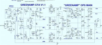
Me bad - error in greenamp schema.
(below is the correction).
I might still reduce currents on this project to accommodate smd and to make it more "green". I assure that no devices will even be warm (besides the outputs). Most small signal devices need no more than 1-4ma.
VERY green , run this in the JUNGLE !! OS
(below is the correction).
I might still reduce currents on this project to accommodate smd and to make it more "green". I assure that no devices will even be warm (besides the outputs). Most small signal devices need no more than 1-4ma.
VERY green , run this in the JUNGLE !! OS
Attachments
Last edited:
Hi OS,
as You connected the driver to the RC filtered rails, I would increase the C102, and 103 to 220-470uF, to get more stable, clean rails.
Sajti
as You connected the driver to the RC filtered rails, I would increase the C102, and 103 to 220-470uF, to get more stable, clean rails.
Sajti

Hi OS,
as You connected the driver to the RC filtered rails, I would increase the C102, and 103 to 220-470uF, to get more stable, clean rails.
Sajti
I begin with layout today. I usually apply electrolytic's with the 2.5mm to 3.5mm option in the output stage board. I only just installed Sprint 6.0 now. Sajti , if you have any recommendations for board size / layout , it would be appreciated. OPS will (as is) be 160mm X 65mm - 4 device TO-3P or MT-200. EF3 drivers will be on a small heatsink with 1 mje340 vbe tracker. CFP drivers will be on the main heatsink , the two transistor Vbe is split , one for the main heatsink - one for the drivers. The Harmon Kardon design it is based on just placed that driver Vbe between the main EF3 drivers ("sandwiched"). Slewmaster output stage is based on this. My concern is the one extra Vbe of the CFP tracker , but I have the main Vbe compensated for that extra thermal compensation in the design.
PS - looks like some boys were bad when I was away. This will push me to make this the BEST of the BEST here at DIYA. I have the Honey Badger and all of the Slewmaster experiences behind me ,
composed 50 nearly perfect designs with no "duds" (except the "infidel" IPS). I will give this out for free , maybe even a new amp for Jason/DIYA. I wish "the bad boys" would of given me some constructive critique to make this even better.
My first 3 layouts will be both the SMD "greenamp" CFA IPS AND the VFA "spooky 2" IPS , a 4 device (200W) and 8 device (400W) output stage , AND a plain "all in one" Lateral MOSFET complete amp based on the "greenamp CFA". 5 boards to do.... "git er' done"!!! OS
Attachments
Last edited:
I have no real recommendation for the layout. I just try to join to Your idea, to make the amplifier as simple, but highest quality as possible.
So I never used capacitance multiplier, just 10ohms+470-1000uF RC filter for the front end. I never had any noise with this solution...
My current project use the smallest possible PCB (pcbway compatible size).
Sajti
So I never used capacitance multiplier, just 10ohms+470-1000uF RC filter for the front end. I never had any noise with this solution...
My current project use the smallest possible PCB (pcbway compatible size).
Sajti
Attachments
Last edited:
I have no real recommendation for the layout. I just try to join to Your idea, to make the amplifier as simple, but highest quality as possible. So I never used capacitance multiplier, just 10ohms+470-1000uF RC filter for the front end. I never had any noise with this solution... My current project use the smallest possible PCB (pcbway compatible size). Sajti
That is nice , Sajti.
Slewmaster is dual row opposing output devices (P channel top / N channel bottom). Just a little unoptimal , one row at top (P or N) of heatsink can get 5C+ hotter than the bottom. This is alright as servo/vbe can compensate , but not fully optimal. A single row will find it's vector of the heatsink at the exact same temperature. Vbe in that single row will find the average temp. along the row. With the fins up/down , you will have to set Vbe at the middle devices , top ones will be hotter and conduct more I , "hogging current". Pass and other esoteric (fancy amps) all use single row for this reason. ALL devices will have matching T vs. Ic. No way around this besides forced air cooling.
DIYA's "Honey badger" is one row inline. OP's , Drivers , Vbe are all the same T. The thermal considerations of greenamp's 2 vbe's , and having both a CFP and EF3 on the same heatsink MUST be carefully considered. Edit - pro amps either alternate P/N or have P vs. N with forced air cooling , there will be some imbalance - devices closest to fan the will be cooler. In any of these sub optimal ways , the differences will increase with dissipation. OS
Last edited:
...NEW will happen on my next few posts. A statement on the current Class G/H state of the art...with critique of the drawbacks for each approach...
I looked forward to this, will it happen?
I wish...some constructive critique to make this even better.
Capacitors C108 and C109 would be better shunted to earth rather than to the power rails.
May not show up in a simple sim without parasitic R, L and C modelled but should improve the PSRR and immunity to RF interference.
I plan to play with the sim today, maybe more comments then.
Best wishes
David
Last edited:
# 1 -I looked forward to this, will it happen?
# 2 - Capacitors C108 and C109 would be better shunted to earth rather than to the power rails. May not show up in a simple sim without parasitic R, L and C modelled but should improve the PSRR and immunity to RF interference. I plan to play with the sim today, maybe more comments then.
Best wishes David
On # 1 - A "paper" .. from the "villager" ?? I hold back on this for two reasons ... I found most class G/H to be a hi-fi unfriendly compromise between performance and economics. My "take on this" might seem negative or harsh. I still have the rough draft in text , I reserve my right to come to a complete mind on this subject, I am still absorbing patents and designs.
# 2 - At last , some "tricks". I feel honored to shunt my pre-driver bases (to earth). I do not say this with any hint of sarcasm. I will explore the merits of this with an open mind. "villagers can be reasonable" even without their pitchforks 😀.
Thank you.
OS
Last edited:
What if you put an opto isolated diode on each transistor and with an Arduino micro monitored the transistor's temp. Then use the temp information to control several fans attached to the heat sink to keep the temp near each other. Also the temp information could be use to set the bias also under the iso opto Arduino. A mega Arduino could also handle this and any Protection circuitry and maybe a remote and or display too. A whole project within itself.
I hold back on this for two reasons ... My "take on this" [may seem] harsh.
Useful to kick around ideas, not harsh to point out real faults and if perhaps you see a 'fault' because you missed the reason then useful to learn this too.
I will explore the merits of this with an open mind.
Harry Dymond's classic "Two Pole analysis" in the JAES looked at where to shunt the compensation capacitors. This looks similar to me, probably not a dramatic improvement but may as well take it, especially before you do the layout.
Another minor improvement, some of the Cordell models are a bit flawed. Remove the EG parameter and let it default. This should improve the temperature behaviour, should you ever do detailed thermal simulations. I normally don't bother with this so I never mentioned it before, just made sure it was correct in my own models. But Toni (ASTX) helped someone with it recently, and a Class G is exactly where a detailed thermal simulation is more likely.
Best wishes David
Last edited:
What if you put an opto isolated diode on each transistor and with an Arduino micro monitored the transistor's temp. Then use the temp information to control several fans attached to the heat sink to keep the temp near each other. Also the temp information could be use to set the bias also under the iso opto Arduino. A mega Arduino could also handle this and any Protection circuitry and maybe a remote and or display too. A whole project within itself.
So you see the problem. Your solution is valid , but would it not be better to solve the problem at the physical level first ? My "partners" at Vzaudio have the arduino based "21 century protection" it used mje340's to detect temperature ... could trigger a fan. As I said Pass and emotive, even Curl amps have inline P/N/P/N arrays. Here you would just have individual device mismatch , no "hot spot" spread in the thermal realm. We must consider ease of construction , some in other forum threads consider Class G/H to be "a complicated beast". I aim to disprove that. I simplified my input stages , while slightly complicating the OPS. Keeping the whole around 120 components. A system monitoring solution is planned by me , But I can't use others IP to do so.
OS
But you must think of the builders. I browse the forum , APEX is tops. APEX has many of the simplest projects. LMJ on ebay is also popular. Parts are also considered. A design must have enough "derating" to accept many devices. My slewmasters will use BCxxx (any of them) or ksc1845/992. Even mpsa 92/42 has been used (not ideal - but will work). Builders even buy the top gain classes where I have to suggest increasing Re.
OS
OS
Ain’t nothing wrong with complexity. Transistors are cheap.
Yeah, they are cheap... My latest preamplifier plan contains 76db small signal transistors (1845/992), maybe I will never decide myself to build it...
About cooling: Few degree difference is not critical. I use LM35 as sensor, and 2 comparators, for half speed/full speed. Each channel has 10cm long heatsink and 8cm fan for cooling. It looks as the processor cooling system...
Sajti
Attachments

But you must think of the builders. I browse the forum , APEX is tops. APEX has many of the simplest projects. LMJ on ebay is also popular. Parts are also considered. A design must have enough "derating" to accept many devices. My slewmasters will use BCxxx (any of them) or ksc1845/992. Even mpsa 92/42 has been used (not ideal - but will work). Builders even buy the top gain classes where I have to suggest increasing Re.
OS
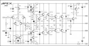
APEX AX11 is my most popular amplifier, but AX22 have 0 builds what do you think why is that.
Attachments
Hi Apex
How easy is it to get those jfets? Once upon a time there were lots of jfet options including matched pairs and complimentary pairs, but now it's like a desert. Jfets are nice devices but I think an amp design will be more popular and buildable without them.
How easy is it to get those jfets? Once upon a time there were lots of jfet options including matched pairs and complimentary pairs, but now it's like a desert. Jfets are nice devices but I think an amp design will be more popular and buildable without them.
Hi Apex
How easy is it to get those jfets? Once upon a time there were lots of jfet options including matched pairs and complimentary pairs, but now it's like a desert. Jfets are nice devices but I think an amp design will be more popular and buildable without them.
You wrote to OS about mHz and MHz and now you are as native English speaker write complimentary pairs instead complementary, strange.
APEX AX11 is my most popular amplifier, but AX22 have 0 builds what do you think why is that.
It's gotta be the JFET's.
Design looks good.
OS
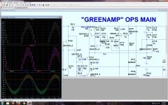
Kind of a "breakthrough".
Still had the class H tracker drivers switching off , even as the main devices did not. Changed just one resistor path to the low rail and added a positive bias shunt resistor (R120 and R118).
The current waveforms became as smooth as the tracking , I knew I did something right . The problem was the reverse leakage of the CFP diode (D103) , even snubbered by (C112) , the leakage forced Q110 into shutoff. I "swamped " it with positive bias (R118). No more crude biasing of Q109 to get my non- switching arrangement - good!
Voltage settling between cycles is also perfect.
Now I get no errata at all from IPS to output. 8ma driver idle and 25ma main idle (Q110 and Q109). And the final good effect is 6ppm 10khz / 10ppm 20khz 4R. Fully transparent !! PS - R118 could be trimmed to set the Idle accurately. Oh . ASC ...set at 10K , deep into class H (below) OS
Still had the class H tracker drivers switching off , even as the main devices did not. Changed just one resistor path to the low rail and added a positive bias shunt resistor (R120 and R118).
The current waveforms became as smooth as the tracking , I knew I did something right
. The problem was the reverse leakage of the CFP diode (D103) , even snubbered by (C112) , the leakage forced Q110 into shutoff. I "swamped " it with positive bias (R118). No more crude biasing of Q109 to get my non- switching arrangement - good!Voltage settling between cycles is also perfect.
Now I get no errata at all from IPS to output. 8ma driver idle and 25ma main idle (Q110 and Q109). And the final good effect is 6ppm 10khz / 10ppm 20khz 4R. Fully transparent !! PS - R118 could be trimmed to set the Idle accurately. Oh . ASC ...set at 10K , deep into class H (below) OS
Attachments
Last edited:
- Status
- Not open for further replies.
- Home
- Amplifiers
- Solid State
- GreenAmp ++ modulated Class G output